The technology for transmitting Ethernet over non-Ethernet has been around for many years. In order to achieve a seemingly simple task, namely: linking network node A and network node B at a distance of X, it is often necessary to develop numerous technologies, protocols and devices. So far, there have been more and more ways to achieve this simple task. From the earliest computer gateway using a 300 baud rate FSK modem to today's advanced Ethernet-over-SONET / SDH system, the purpose of this work has remained basically unchanged. However, efforts in various aspects in recent years have further promoted the technological advancement in solving this task and made it cater to today's needs. Some developed "branch" technologies have failed miserably, while others have gained widespread use worldwide, such as DSL technology. How can we be sure that emerging branch technologies will survive forever? From the "hindsight" perspective, the technology that can last forever can usually achieve an ideal between service quality, reliability, available bandwidth, scalability, interoperability, ease of use, equipment costs, and operating costs. Balance. However, the technology that performs poorly in any aspect will not be widely adopted, and will eventually disappear or only be applied in a small area. From these aspects, we can evaluate the emerging Ethernet-over-PDH (EoPDH) technology.
In summary, EoPDH transmits local Ethernet frames over the existing telecommunications copper infrastructure through quasi-synchronous digital hierarchy (PDH) transmission technology. EoPDH actually integrates many technologies and new standards, allowing operators to make full use of the network composed of their traditional PDH and SDH (Synchronous Digital Hierarchy) equipment to provide Ethernet services. In addition, the EoPDH standard also paves the way for network interoperability and the gradual transition of operators to Ethernet. The standardized technologies used in EoPDH include: frame encapsulation, mapping, link aggregation, link capacity adjustment, and management messaging. Common operations of EoPDH devices also include marking data for separating virtual network services, prioritizing user service data, and a large number of high-level applications (such as DHCP servers and HTML user interfaces).
The process of frame encapsulation is to put Ethernet frames in the form of payload inside an auxiliary format for non-Ethernet transmission. The main purpose of encapsulation is to identify the start byte and end byte of the frame. This process is called frame division. In an actual Ethernet network, the frame separator and length fields play the role of frame division. Another function of encapsulation is to transform intermittent ("burst") Ethernet transmissions into a smooth, continuous data stream. In some technologies, encapsulation also plays the role of error checking: error checking can be achieved by adding a frame check sequence (FCS) to each frame. There are many existing packaging technologies, including advanced data link control (HDLC), SDH link access specification (LAPS / X.86) and general framing specification (GFP). Although in theory any packaging technology can be applied in EoPDH, only GFP has the most application advantages and has become a widely accepted packaging method. Most EoPDH devices also support HDLC and X.86 packages. These two technologies have good interoperability with traditional systems.
The GFP defined by the ITU-T G.7041 standard uses header error control (HEC) technology to divide the frame. For other encapsulation protocols that use start / stop tags (such as HDLC), when the start / stop tags are present in the user data, it usually causes bandwidth expansion and must be replaced with a longer escape sequence. By using the HEC frame division technology, GFP does not need to perform flag replacement in the data stream. This allows GFP to achieve stable and predictable load throughput. For operators who need to guarantee throughput to customers, this is very important. Figure 1 shows the frame format of the mapped GFP frame (GFP-F) and comparison with the HDLC frame. Please note that the number of bytes in the local Ethernet is the same as the number of bytes in the GFP-F encapsulated Ethernet. This small detail makes the rate matching easier. Once the Ethernet frames are encapsulated into a high-level protocol (for frame division), they can be mapped and transmitted at any time.
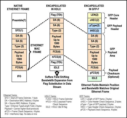
Figure 1. HDLC and GFP frame structure comparison
The mapping process is to put the encapsulated Ethernet frame in a "container" for transmission on the link. Different technologies have different names for these containers. In summary, the main purpose of the container is to align information. Some containers also provide management / signaling channels and link quality monitoring functions. Containers usually have strict format definitions, and perform cost monitoring and business management at predetermined locations. Examples of SDH containers include C-11, C-12 and C-3. "Trunk road" and "branch road" are also commonly used to refer to PDH containers. Examples of PDH include DS1, E1, DS3 and E3 framing architecture. In most cases, one or more low-rate containers can form ("map") a higher-rate container. In SONET / SDH networks, people have also defined virtual channels (VC) and tributary units, and proposed some basic containers to achieve greater flexibility.
The frame format of the basic DS1 and E1 branches is shown in Figure 2. Please note that each frame is reserved for framing information. The purpose of framing bits (or bytes) is to provide alignment information to the receiving node. The structured frame format repeats every 125ms. 24 DS1 frames form an extended super frame (ESF). The 16 E1 frames are an E1 multiframe. By using this framing information, the receiving node can convert the received bits into a single time slot or channel. In traditional telephone technology, each time slot (or channel) can only carry the quantitative information of a single telephone call. When transmitting packet data, all time slots can be used as a single container.
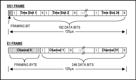
Figure 2. Example PDH frame format
When the encapsulated Ethernet frame is transmitted on the PDH, the time between Ethernet frames is filled with a blank number. When the GFP encapsulated frame is transmitted in DS1 or E1, the transmitted information is byte aligned. The alignment is slightly more complicated than DS3. The ITU-T G.8040 standard defines four-byte alignment rules for DS3 links. Figure 3 shows an example of a GFP-encapsulated DS1 Ethernet. Please note that the position of the Ethernet frame after encapsulation is independent of the DS1 framing format bit ("F") and is byte-aligned. Although there is no bearer information in the picture, the X43 + 1 scrambling algorithm has been applied to the bearer information before transmission. Similar mapping and scrambling techniques are also used in SDH shipping containers. The ITU-T G.707 standard describes in detail how to directly map Ethernet frames to SDH.
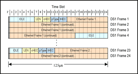
Figure 3. GFP-encapsulated Ethernet frames are mapped to DS1 Super Extended Frames (ESF)
Link aggregation is the process of integrating two or more physical links into a single virtual link. Link aggregation is actually a structured method for distributing data on multiple signal channels, aligning the information received from different channels with different latency, and then recompiling the data and handing it over to the higher-level protocol. Link aggregation is not a new technology. Multilink Frame Relay (MLFR), Multilink PPP (MLPPP), Multilink Specification (X.25 / X.75 MLP) Inverse MulTIplexing over ATM (IMA), etc. are just link aggregation technologies. Among them, IMA and MLFR are the most widely used.
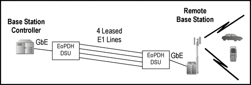
Figure 4. Link aggregation application example
Link aggregation is mainly used to increase the bandwidth between two network nodes (as shown in Figure 4) and slow down the transmission to the high-throughput PDH or SDH branch. Some form of link aggregation, such as First Mile Ethernet (EFM, see IEEE 802.3ah), binds multiple DSL links together to improve throughput at a given distance, and more importantly Effectively increase the service distance on the basis of fixed throughput.
The main link aggregation technology used in today's SONET / SDH networks is called Virtual Concatenation (VCAT), which is defined in the ITU-T G.707 standard. This standard uses existing overhead channels as VCAT overhead. However, when applying the concept of VCAT to the PDH network, the existing management channel is not enough, and a new space needs to be allocated to the VCAT overhead. The location of the VCAT overhead in the DS1 link can be seen from Figure 5. The overhead byte occupies the first time slot of each DS1 super extended frame that has been concatenated.
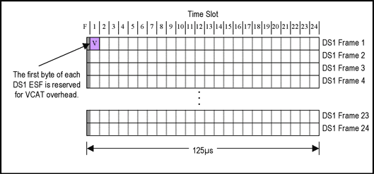
Figure 5. DS1's Virtual Concatenation (VCAT) overhead
The management channel created by the VCAT overhead bytes will be used to convey information about each link. For each transmitted DS1 super extended frame or E1 multiframe, a VCAT overhead byte will be attached to each link. Therefore, 1/576 of the available bandwidth of DS1 will be used for VCAT overhead.
The definition of VCAT overhead is shown in Figure 6. The 16 bytes shown in the figure are attached to 16 consecutive DS1 super extended frames one byte at a time for transmission. These bytes are repeated every 48ms.
The lower byte of the VCAT overhead byte includes a multiframe identifier (MFI), which is used to align frames with different transmission delay times. The high byte contains a unique control symbol (the 16 values ​​of the multiframe indicator). This high byte is called VLI and contains virtual concatenation and link capacity adjustment mechanism (LCAS) information.
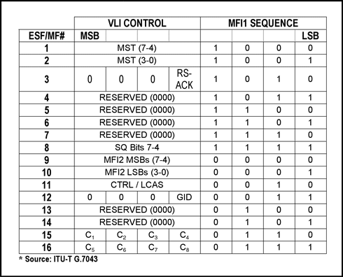
Figure 6. VCAT overhead byte definition in DS1 / E1
Cascaded links are also called virtual cascaded groups (VCG). All members of the virtual cascade group have their own VCAT overhead channels, as shown in Figure 7. Figure 7 also shows the data location of the members of the virtual cascade group. The complete EoPDH link aggregation specification is described in the ITU-T G.7043 standard.
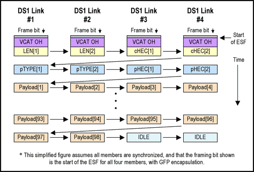
Figure 7. Data distribution of a four-member DS1 virtual cascade group
Link capacity adjustment adjusts aggregate throughput by adding or deleting logical links between two nodes. When adding or deleting members of a virtual cascade group, the two end nodes use LCAS to negotiate. LCAS uses the VCAT overhead channel to perform the negotiation function. With the help of LCAS, the bandwidth of the virtual concatenation group can be increased without interrupting the data flow. In addition, the faulty link will be automatically deleted to minimize the impact on the business. For the complete standard of LCAS, please refer to ITU-T G.7042 / Y.1305.
Management messaging is mainly used to communicate the status between two network nodes, report faults, and test connectivity. In an operator's Ethernet network, these are often referred to as "Operation, Management, and Maintenance" (OAM). The importance of OAM is that it can reduce the burden of network operation, verify network performance and reduce operating costs. OAM is closely related to the service level that users get. OAM will automatically detect network performance degradation or failure, automatically perform recovery operations when necessary, and record the length of the failure.
The messages exchanged are called OAM protocol data units (OAMPDU). The industry has defined 16 OAM protocol data units for different purposes: monitoring status, checking connectivity, detecting faults, reporting faults, locating errors, returning data, and preventing safety leakage holes. The International Telecommunication Union (ITU) has defined the layer of the management domain, so that the user's network management data can be managed by the operator OAM through various point-to-point links. The International Telecommunication Union also defines the interaction between management entities so that multiple operators can seamlessly manage end-to-end data flows. The Institute of Electrical and Electronics Engineers (IEEE), International Telecommunication Union (ITU) and Metro Ethernet Forum (MEF) have jointly defined the format and usage of OAM protocol data units. Applicable standards include IEEE 802.3ah and 802.3ag, and ITU-T Y.1731 and Y.1730.
The labeling function allows operators to identify a customer's data service anywhere on their network. The corresponding technologies include: VLAN tags, multi-protocol label switching (MPLS) and general multi-protocol label switching (GMPLS). All these technologies insert several identification bytes in each Ethernet frame at the entrance (where the service data first enters the network), and then remove this information when the frame leaves the network. Each technology also provides other functions than labels. For example, VLAN tags also include data prioritization fields, and MPLS / GMPLS can also be used to "switch" data (eg, determine the destination of a frame and send it to an appropriate location in the network).
The priority function can be used to buffer Ethernet frames anywhere on the network. When the frame is waiting in the buffer, the highest priority service data will be transmitted first. You can think of it as requeuing the waiting vehicles when the red light is on. When the output rate of a node is less than the input rate, buffering is required. Usually this situation is caused by network congestion and will not last long. If the output rate of a node is lower than the input rate for a long time, flow control must be used to slow down the data from the data source. The latter case is more common when local area network (LAN) business data enters a wide area network (WAN) link (bandwidth costs are higher over long distances). This node is usually called the "entry node" and plays an important role in prioritizing business data. The two concepts of priority and flow control are the cornerstones of quality of service (QoS). Many people will have this misunderstanding: Priority provides a good "unblocked pipeline" for high-priority business data. In fact, priority and scheduling simply allow "more important" business data to be transmitted earlier at the buffer node location. Good service quality should also consider other factors.
High-level applications are executed by a network node, and can be used for various purposes. Layer 2 (data link layer) and layer 3 (network layer) applications are the most common. Layer 2 applications include some protocols that affect point-to-point communication, including address resolution protocols (ARP / RARP / SLARP / GARP), point-to-point protocols (PPP / EAP / SDCP), and bridge protocols (BPDU / VLAN). The three-tier application contains protocols for communication between hosts, including bootloader protocol (BOOTP), dynamic host configuration protocol (DHCP), Internet group management protocol (IGMP), and resource reservation protocol (RSVP). The application of the four-layer (transport layer) protocol is not common, but usually only serves high-level applications.
There are not many seven-layer (application layer) protocols used by EoPDH equipment. These protocols include the Hypertext Transfer Protocol (HTTP) used to provide HTML user interface web pages, and the Simple Network Management Protocol (SNMP) that provides automatic device monitoring through users' network management tools.
Service quality and reliability: Ethernet OAM greatly improves the service quality of data transmission using technologies such as DS1 / E1 or DS3 / E3. Under monitoring, link performance degradation and link failures can be reported automatically, and recovery operation is also automatic. Since the transmission base is a PDH network, existing PDH management tools can also be used. In the future, PDH and Ethernet management tools can be combined to bring greater transparency and unify the management interface.
Bandwidth requirements and scalability: The EoPDH link aggregation function can expand the bandwidth used for transmission (from 1.5Mbps to 360Mbps) in 1.5Mbps increments. This bandwidth range covers all close-access applications, including high-bandwidth applications like IPTV. The use of a committed information rate (CIR) circuit at the entry point achieves a better bandwidth granularity that serves the end user.
Interoperability and ease of use: Because EoPDH technology utilizes existing PDH technology, and PDH has established an infrastructure based on rich experience and equipment. Trained technicians are already familiar with the use and maintenance of PDH, and PDH test equipment is relatively easy to obtain. Traditional equipment can be used for transmission, switching, and monitoring of PDH auxiliary channels. When EoPDH is applied to a traditional SONET / SDH network, the interoperability it achieves brings significant cost advantages. The combination of these technologies is called Ethernet-over-PDH-over-SONET / SDH or EoPoS. EoPoS reduces costs by allowing the reuse of traditional TDM-over-SONET / SDH equipment. Compared with replacing existing SONET / SDH nodes with "next-generation" Ethernet-over-SONET / SDH (EoS) equipment, PDH auxiliary channels can be implemented through traditional ADM to low-cost CPE or EoPDH VCAT / LCAS link aggregation equipment.
Equipment cost and operating cost: Since existing equipment can be used for network transmission, only the entry node needs to enable EoPDH technology. Normally, to enable EoPDH, you only need to add a small DSU (modem / media converter). Advanced Ethernet OAM also reduces operating costs through link monitoring and rapid fault location. Future devices can use Ethernet-based protocols for self-configuration, greatly simplifying the installation process. EoPDH can not only save the operator's cost, but the service fee of multiple (aggregated) DS1 or E1 links of users will be much lower than that of a single high-speed link (such as DS3), so that the cost of the operator's customers is also saved.
Baby Fan, a ideal design for baby. This portable Usb Mini Fan is a good product to use on baby bad, baby stroller or other uses. The wind is gentle and smooth, you don`t need to worry the baby will be cold. This Mini Fan is also suitable for the elder people in summer. The Usb Fan shell can be detachable and washable. With large battery capacity, this rechargeable fan can work about 2 hours every time after full charging. With a USB line, this small fan can be recharged by direct current or a computer or a power bank. This rechargeable mini baby fan is very convenient. The mini baby fan uses a brushless DC motor to provide strong wind while quiet, energy-saving and stable operation.Others will be not influenced.
Baby Fan
Stroller Fan,Baby Stroller Fan,Fan In Baby Room,Portable Fan For Stroller
SHENZHEN HONK ELECTRONIC CO., LTD , https://www.honktech.com
