
Keywords: RF power amplifier, control, circuit principle
In order to meet the requirements of long communication distance, modern military and civilian ultra-short wave communication stations have large RF power output, and RF power amplifiers generally work in high current and high power states. In order to make the power amplifier circuit work safely and reliably, a comparison is set in the power amplifier circuit The perfect automatic control circuit for power amplifier protection, including high-voltage standing wave ratio protection, high-temperature protection in the machine and low voltage drop power protection circuit, enables the transmitter's RF power amplifier level to output large RF power under the premise of ensuring safety.
1 Voltage standing wave ratio power protection circuit
1.1 Function When the transmitter antenna fails, the RF power output by the transmitter cannot be effectively transmitted, which will generate a large transmit power and seriously affect the safety of the power amplifier level. Therefore, a high-voltage standing wave ratio protection circuit is installed in the transmitter control circuit. When the voltage standing wave ratio is higher than a certain value, the RF power output is controlled to reduce the effective protection power amplifier circuit. The circuit is shown in FIG. 1.
1.2 Circuit principle Figure 1 is the principle circuit of voltage standing wave ratio power protection. Its working principle is to detect the reverse power voltage output by the directional coupler at the output end of the transmitter power amplifier. After processing by the relevant circuit in the power supply of the power amplifier, it is sent to the transmitter control circuit XP1 / 12A, and then compensated by the reverse power detection voltage. The circuit is added to the N20B amplifier and added to the non-inverting input terminal of N20A through N20B. When the voltage of this input terminal reaches about 300mV, (when the output of the amplifier and the impedance of the antenna are mismatched, the voltage standing wave ratio is greater than 2.5: 1), The output voltage of N23A is greater than 6.2V, making VD5 regulator tube and V3 conductive. Turning on V3 turns on VD6, which lowers the level of the N23B non-inverting input and the voltage at the output of N23B, so that the power DC control voltage applied to the Vx input of the analog multiplier N24 drops to a certain level. The output power of the RF power amplifier is reduced to a certain value, and the RF power amplifier is protected.
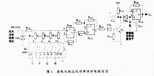
When the voltage standing wave ratio is not greater than 2.5: 1, the reverse power detection voltage is small, and the output voltage of N23A is not enough to turn on VD5. Therefore, VD6 is also cut off due to reverse bias, and it is input to the same phase at N23B. Only the normal power DC control voltage set on the front panel is added, the voltage applied to the Vx input terminal of the analog multiplier is also a normal value, and the transmitter RF power amplifier has a normal output power.
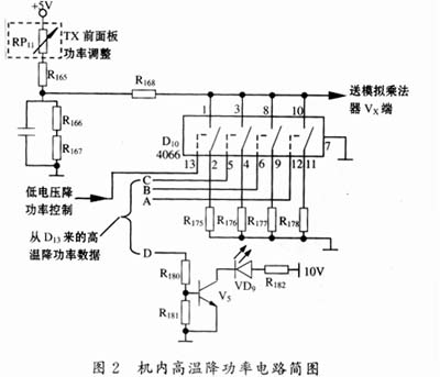
2 The high-temperature power protection dual-band radio in the machine is equipped with temperature sensors at the RF power amplifier level and the power amplifier voltage stabilization module. When the temperature in the machine exceeds 65 ℃, the monitoring module microcomputer controls the fan to speed up; when it exceeds 80 ℃, the monitoring microcomputer Control the operation of the high-temperature power reduction circuit in the transmitter control circuit to reduce the RF output power. The schematic diagram of the high-temperature power reduction circuit inside the machine is shown in Figure 2.
It can be seen from Figure 2 that the high-temperature drop power control in the machine is essentially the power DC control voltage set by the Tx (transmitter) front panel power adjustment potentiometer RP11, which is connected to one (or several) switches of R168 and D10. Through the connected resistor (R175 ~ 178) for voltage division, the voltage sent to the Vx terminal of the analog multiplier is reduced, thereby reducing the RF output power.
D10 (MC14066) is a four-way analog electronic switch whose control terminals (A, B, C) are controlled by the binary data output by the monitoring module microcomputer through the transmitter data interface circuit. If the temperature continues to rise, the binary number gradually increases, so that the resistance of D10 is increased, and the RF output power gradually decreases.
The terminal D controls the high-temperature indication circuit inside the machine. When the D terminal is high level (high temperature in the machine), V5 is turned on, so that the VD9 LED indicates high temperature.
3 The low voltage drop power transmitter control circuit is equipped with a power supply voltage monitoring circuit (on the audio processing circuit diagram). Once the power supply voltage is detected, the power DC control voltage is reduced, thereby reducing the RF output power. The circuit diagram is shown in Figure 3.
It can be seen from Figure 3 that the base regulated power supply outputs +3 0V (unregulated) voltage, which is sent to XP2 / 4A of the transmitter's sound control board module after the monitoring module. This + 30V voltage produces a voltage drop on RP10, R110, R113. Take the voltage drop on R113 (about 1.51V) and add it to the inverting input of N19B voltage comparator via R114 (set V2); transmitter sound control board The internal + 10V (regulated voltage) voltage is divided by R111 (18k) and R112 (1.8k), and the voltage on R112 (about 0.87V) is added to the non-inverting input terminal of N19B (set V3). When the power supply voltage is normal, adjust RP10 so that V2> V3, then N19B output low level, this level is connected to D10 / 13 (see Figure 2), so that D10 / 1.2 pin is disconnected, the transmitter normally outputs RF power ; When the power supply voltage is reduced, the voltage on R113 is also reduced, so that V2 <V3, N19B output high level, this level makes D10 / 1.2 foot connected, the power DC control voltage is divided by R168 and R175 It is supplied to the VX input terminal of the analog multiplier to reduce VX, thereby reducing the RF power output by the transmitter.

The capacitor C52 in FIG. 3 is to ensure that the V2 <V3 of the N19B is ensured only when the power supply voltage is reduced. Unstable power supply voltage fluctuations are filtered out. VD1 and R114 are set to ensure that the N19B voltage comparator works quickly, R115 plays a positive feedback role, and VD1 provides a channel for the rapid discharge of C52.
4 Conclusion The RF power amplifier circuit has been proved by practical application. The circuit design is novel and the circuit is simple and practical. It can automatically control the RF power amplifier in the case of high-current and high-power RF impedance mismatch, high internal temperature and reduced power supply voltage. Protect the RF power amplifier circuit, increase the reliability and service life of the radio.
2 Edited by Yanli and Wangyou Village. Modern communication system. Beijing: Electronic Industry Press, 2001
3 Edited by Wang Baoliang. Ultrashort wave air communication station. Xi'an: Air Force Telecommunication Engineering College, 1996
Function: The LED Bicycle Lights has 1-5 modes;
Feature: The Led Bicycle Lights usually high power and super bright;
Trait: The products are waterproof, shockproof;
Battery: AA/AAA/rechargeable battery/solar battery;
Method of application: Simple on/off push button operation;
Range of application: The LED Bicycle Lights for emergency events, camping, outdoor activities;
Adervantages: Our products are saled with factory price, and the quality can guarantee, lastly we provide warranty for 1 year.
LED Bicycle Lights
Led Bicycle Lights,Rechargeable Bicycle Flashlight,Rechargeable Led Bike Lights,Led Bike Light
Ningbo Henglang Import & Export Co.,Ltd , https://www.odistarflashlight.com