
In modern measurement systems, cameras and various sensors often work together, requiring precise synchronization. This example presents an aerial photography system that integrates a camera equipped with a CCD (Charge-Coupled Device) image sensor, an Inertial Measurement Unit (IMU), and a GPS (Global Positioning System) module. A synthesized circuit generates a trigger signal to ensure accurate synchronization at the optimal frame rate. The GPS provides geographical location data, while the IMU offers spatial orientation information, including angular and acceleration measurements along three axes using a gyroscope, magnetometer, and accelerometer.
Figure 1 illustrates the system used for aerial imaging. It consists of four Atmel area scanning CCD modules, a linear image sensor, two Dalsa PCI frame capture cards, a measurement unit, a clock conditioning circuit, and a microcontroller. During development, the trigger signal was monitored using a Tektronix digital oscilloscope.
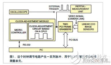
The trigger signal is essential for synchronizing all components in this system. The clock conditioning circuit sends an external trigger pulse to the frame capture card, which then generates the necessary trigger signal for the system. A video module containing the image sensor receives this signal and captures images accordingly. Each frame capture card stores the captured image in onboard memory before capturing the next one.
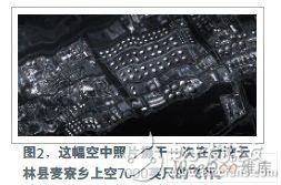
External trigger pulses also control the operation of the sensor, GPS, and IMU. Figure 2 shows a high-altitude photograph taken from 7,000 feet above Maizi Township in Yunlin County, Taiwan, using the external trigger circuit to synchronize the linear sensor and measurement unit.
To achieve the best frame rate, the circuit must adjust the frequency of the external trigger clock. The CCD sensor in the linear image sensor module has 12,288 pixels, each measuring 5 mm x 5 mm, producing an image of approximately 500 lines per frame. The maximum output rate of the CCD image sensor is 320 Mpixels per second. The image data is transmitted to the frame capture card via a Camera Link interface and then sent to a PC through the PCI bus.
The clock conditioning circuit generates an externally triggered clock pulse. It uses an Altera CPLD (Complex Programmable Logic Device), designed using Altera's development software to simulate trigger signals and optimize the circuit. This circuit can provide up to 15 different trigger frequencies for the system.
The system's Atmel microcontroller features 256 bytes of RAM and 8k bytes of programmable flash memory for storing programs. It communicates with the PC via an RS-232 interface, allowing it to receive commands and report status. This process involves generating and decoding parameters for the trigger signal. Additionally, the microcontroller sends instructions to the digital timing adjustment circuitry, enabling changes to the external trigger's pulse frequency.
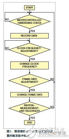
With 15 available trigger frequencies, the system can fine-tune the frame rate of the CCD image module. The external trigger signal also activates the measurement unit to record and store spatial parameters. Figure 3 outlines the algorithm used to determine the optimal trigger frequency, where the frame rate is directly proportional to the trigger frequency.
The Inertial Measurement Unit (IMU) plays a critical role in the system and must be closely aligned with the frame capture card. If the external trigger frequency is set to 1 kHz, each frame capture card can capture 1,000 frames per second, and the IMU samples data at 1,000 samples per second. Experimental results from aerial photography confirm that the system successfully synchronizes all sensors, ensuring accurate and reliable data collection.
women's digital watch,ladies smart watch ,round women's smart watch,stylish women's smart watch
Dongguan Yingxin Technology Co., Ltd. , https://www.dgyingxintech.com