
In portable and miniaturized consumer products, the use of Class D audio power amplifiers has become very common. This paper introduces the design principle of the output low-pass filter of the class D audio amplifier, and gives the calculation method and the considerations of the selection of the inductance and capacitance values ​​in the filter. This article also uses National Semiconductor 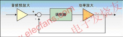
This article refers to the address: http://
Figure 1: The composition of a single-chip Class D audio amplifier.
Currently, switching mode (Class D) audio power amplifiers are common in most portable and miniaturized consumer products such as MP3, portable DVD and flat panel displays. Due to the lower power consumption of the Class D amplifier, higher efficiency can be achieved. It extends the battery life of portable devices and reduces the size of the heat sink and the area of ​​the PCB, saving system cost. Therefore, many large flat panel displays and consumer audio products are more willing to use such amplifiers.
However, Class D amplifiers are based on digital modulation techniques that use high switching frequency signals to achieve efficient amplification of the signal. The modulation frequency is typically up to hundreds of kHz, which is well beyond the audio range. Welcome to reprint, this article from the electronic enthusiast network ( http:// )
Since we need to recover the desired real audio signal (music) from the digitized or modulated signal, an output low pass filter is required to filter out the high frequency components to reproduce the real analog signal that matches the human auditory system.
Here, we will elaborate some considerations and recommendations for the output low-pass filtering design.
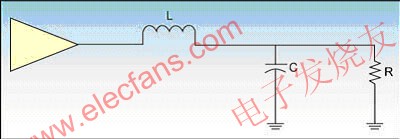
Figure 2: BTL half-circuit model.
Class D Amplifiers: Monolithic Class D audio amplifiers include analog audio inputs, modulators, power transistors, etc. (see Figure 1).
Output Filter Design: Since we need to recover the required audio signal, it is important to design an excellent output low-pass filter to filter out high frequency components (unwanted signals) and obtain high quality analog sound. We must design an output filter with a specific reactive output impedance to match the load impedance. The BTL half-edge circuit model is shown in Figure 2.
The output filter of a Class D amplifier is typically a second-order, LC-type Butterworth filter. This is because the Butterworth filter provides a relatively flat passband frequency response and requires a small number of components. Here is a reference graph showing the LPF response of the Butterworth, Bessel and Chebyshev type filters (Figure 3).

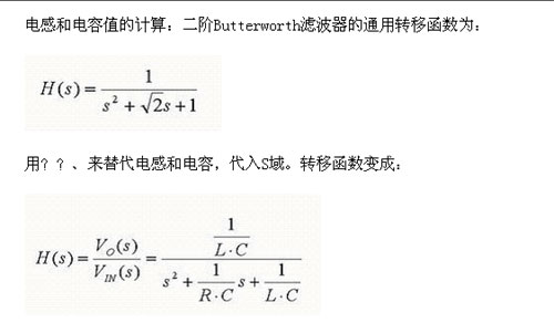
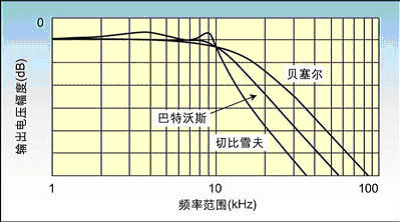
Figure 3: Comparison of low-pass filter responses of Butterworth, Bessel, and Chebyshev filters.
For an actual BTL circuit, the output filter is shown in Figure 4.
The derived BTL filter equation is:

According to the above equation, Table 1 lists the inductance (L) value and capacitance (C) value corresponding to the specific fc and RL.
Inductor selection: In the output filter, the inductor is the key component. It is related to the DC resistance and rated peak current specifications of Class D audio power amplifier systems. The DC resistance reflects the efficiency of the total output power. The efficiency of the system can be estimated by:

Where: RL is the DC resistance of the speaker, RDSON is the transistor on-resistance of the output driver inside the Class D amplifier; RIND is the DC resistance of the inductor.
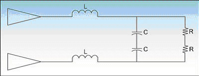
Figure 4: Actual BTL circuit output filter.
In addition to choosing the appropriate inductor value to achieve a particular cutoff frequency, the maximum DC resistance of the output inductor is another key parameter that affects overall efficiency. Therefore, it is strongly recommended to use an inductor with a lower DC resistance.
Another important parameter that must be considered for an inductor is its maximum rated current. If the inductor's rated current is not sufficient to maintain the output current of the device, the inductor will short-circuit. This will cause damage to the device or speaker due to large currents.
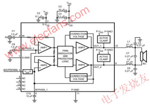
Figure 5: Application block diagram of the LM4680 (determination of the value of the LC output filter).
Finally, it is worth mentioning that in order to reduce distortion, EMI and crosstalk, shielded inductors (eg pot core inductors) are recommended.
The pot core is known for its excellent shielding performance because the inductor coil is completely surrounded by the core except for the two narrow slots used to traverse the wire. Welcome to reprint, this article from the electronic enthusiast network ( http:// )
Capacitor Selection: One of the most important parameters in evaluating high-frequency chip capacitors is Q (quality factor), or the associated equivalent series resistance (ESR).
Simply put, ESR is a measure of all series and parallel losses in a capacitor at a given frequency. In theory, the "ideal" capacitor will have an ESR of 0 Ω and is purely reactive, with no real (resistive) component. The current flowing through the capacitor will just exceed the voltage across the capacitor by 90 at all frequencies.
8 Inch LED Downlights is can be detachable in 2 parts. For 8 inch LED Downlights, we can do thw watt from 10W to 40W. 10W, 15W, 18W, 30W, 40W are the conventional product. 8 inch 30W are the popular one.
The 8 inch downlight use Samsung SMD5630 chips with Philips or Lifud driver. Use high quality PC cover, and adopts precision die-casting aluminum for the module, nice heat dissipation.
Dimmable function can also provide. White, black, silver corlor for option. High CRI >80Ra. High PF >0.95. 100lm/W.
For the 8 inch Led Downlights, it can also up to IP54 protection level. All the LED Downlights is CE RoHS approved. 8 inch LED downlights is easy to transport and install. 185-210mm hole size is suitable for 8 inch LED downlights.


8 Inch LED Downlights
8 Inch LED Downlights, 8 Inch Dimmable LED Downlights, Aluminum 8 Inch LED Downlights, LED Recessed Lighting Downlight
SHENZHEN KEHEI LIGHTING TECHNOLOGY CO.LTD , http://www.keheiled.com