
Abstract: The design of the network experiment platform node of the body electrical control system of a CAN bus is insufficient. For example, the node is too large, and the car and node division are not reasonable. It is mainly designed for the hardware interface circuit part of the experimental bench. Based on the re-optimization of the core components of the interface circuit, the program is reprogrammed in combination with the hardware functions and the operating environment of the selected device. The feasibility of the scheme is verified by experiments, which makes the node more practical and more complete. It provides a new idea for the design of hardware interface circuit of body electrical control system based on CAN bus, and provides good experimental equipment for teaching work.
Key words: CAN bus; body appliance; control network; optimization design
This article refers to the address: http://
With the increasing development of automotive electronics, the use of traditional communication modes will inevitably lead to complex wiring of automotive electrical appliances and difficulties in maintenance testing. The proposed CAN bus has made it possible to solve this problem. The CAN (C0ntmller Area Network) bus is a serial communication protocol proposed by Bosch in Germany in the 1980s to realize the communication between many electronic modules on modern automobiles. It is the only bus with international unified standards. However, since the domestic research on CAN bus started very late, there are not many domestically produced products. Therefore, based on the multiple purposes of scientific research teaching and product development, the literature developed a test bench for body electrical control system based on CAN bus. Based on the CAN bus, the test bench simplifies the control network of the vehicle body electrical appliance with a car body appliance and reduces the wiring harness. The experiment also proves the correctness of the developed system and the feasibility of the CAN bus replacing the traditional body harness. The practical significance of the successful development of the experimental platform is very important, but the following deficiencies should be improved: 1) The test bed divides the lamp control node into two nodes: the headlight and the rear lamp, so that not only is not completely complete in communication. Using the interface of the microcontroller, we must also consider the priority of the nodes before and after, complicating the design of the software. 2) The pin current of the MCU is too small to drive high-powered lamp and door motor power devices. The test bench uses drive chips, relays and fuses to realize the function. This design interface circuit makes the overall volume of the node large and inconvenient. Car. This paper mainly proposes solutions to the above two problems. Firstly, the node is reclassified, and the hardware environment is rebuilt based on AT89S52 microprocessor and CAN controller SJAl000. Then the AT89S52 is taken as the core, and the operating environment of the selected device is improved. program.
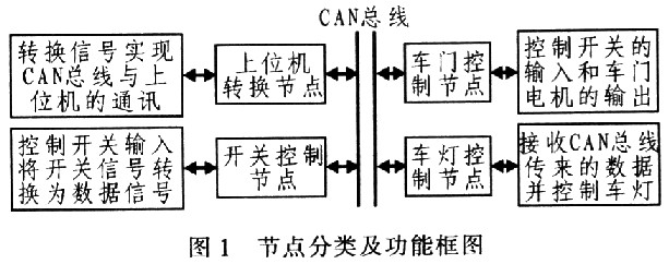
1 Body appliance control system node classification and its function The control system divides the body appliance into four classes: upper computer conversion node, switch control node, vehicle lamp control node and door control node. The electrical equipment and signals to be transmitted by various types of nodes are as follows: 1) The upper computer conversion node: converts the CAN protocol signal into the RS232 protocol signal output, which is received by the serial port of the upper computer; 2) the switch control node: the switch switch node needs Each switch input converts the physical switch signal into a data signal through a single chip microcomputer; 3) the lamp control node: receives the controllable data uploaded from the bus, and converts the data to control the state of each lamp of the lamp, and controls the body appliance Mainly high beam, low beam, fog light, turn signal, reverse light, brake light and other lamps; 4) door control node: control the switch input of the door and the output of the glass lift motor. The classification and function of the nodes are shown in Figure 1.
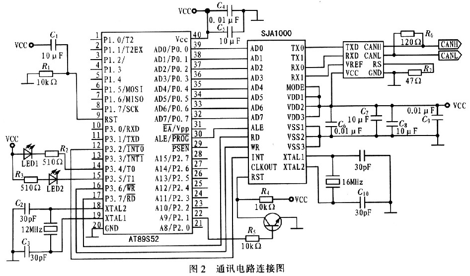
2 system hardware circuit design The hardware communication circuit part is composed of single chip AT89S52, CAN controller SJAl000, CAN transceiver PCA82C250. The hardware design of any type of node is composed of the communication circuit and the interface circuit, and the CAN controller and the connection circuit between the transceiver and the single chip are shown in FIG. 2 . In order to make a signal on the bus, the system can respond quickly, and the microcontroller and SJAl000 use separate crystal oscillators. The crystal frequency of SJAl000 is 16 MHz, and the crystal frequency of the MCU is 12 MHz. This allows the CAN controller to receive or transmit data faster than the processing speed of the MCU. The data from the bus or the data to be sent to the bus can be temporarily stored in the data. In the SJA1000 buffer, it waits for the microcontroller to process or automatically send it to the bus.
2.1 Upper computer conversion node interface circuit In the upper computer conversion node, the function of the interface circuit is mainly to convert the data into data conforming to the RS232 level protocol, which can be received by the host computer serial port. Since the logic levels "1" and "0" in the data output from the microcontroller are represented by 5 V and OV, respectively, the logic "0" level of the RS232 level ranges from -5 to 15 V, and the logic "1" is charged. The flat range is +5~+15 V, so the MAX232 is used for level conversion, and the function of the interface circuit of the upper computer conversion node is completed. Figure 3 shows the interface circuit of the upper computer conversion node.

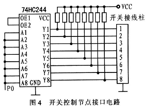
2.2 Switch Control Node Interface Circuit In the switch control node, the function of the interface circuit is mainly to convert the multi-switch state in the node electrical device into a digital signal, and realize the conversion from the vehicle power supply 12 V to the 5 V power supply used by the single chip microcomputer. The 74HC244 selected by the interface circuit is a CMOS 8-bit bus transceiver, which is mainly used when the switch input is used, and the switch and the SJA1000 share the switch of the P0 port of the single chip; the power conversion is mainly realized by the voltage regulator LM7805. Figure 4 shows the switch control node interface circuit.
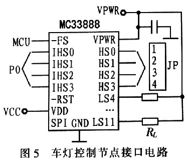
2.3 Lamp control node interface circuit In the lamp control node, the function of the interface circuit is mainly to realize the control of the lamp power appliance through the CAN bus transmission data. The current flowing from the pin of the MCU is very small, and the lamp cannot be directly driven. If the driving circuit and the relay are used to complete the driving function of the lamp, the control node of the lamp will inevitably be too large, and it is not practical and beautiful. The interface circuit uses MC33888 device. The device integrates four high-end drivers and eight relays or LED drivers. It is a controllable network with online diagnostics, error communication with the microcontroller, and softening of faults. Figure 5 shows the lamp control node interface circuit.
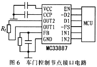
2.4 Door Control Node Interface Circuit The function of the door control node interface circuit is similar to that of the lamp control node interface circuit. It also converts the small current signal output from the single-chip microcomputer into an electric signal that can drive high-power appliances, and completes the corresponding work. This circuit uses the MC33887 device. The device consumes low power, with a current of 25 mA in standby mode and an output short-circuit of more than 8 A. Figure 6 shows the door control node interface circuit.
3 system software design The communication protocol of any CAN bus system is composed of physical layer protocol, data link layer protocol and application layer protocol. The hardware structure of SJAl000 and PCA82C250 guarantees the physical layer and data link layer of the protocol. For the application layer, different protocols have been developed in different application areas, including CANopen, DeviceNet and SAE J1939. The application layer protocol determines the scalability of the CAN bus system. Appropriate allocation of the CAN application layer and application to the software structure can improve software compatibility.
The various types of nodes in this design can be divided into main programs and subprograms. The purpose of the main program is to monitor the status of each appliance in this node. It is programmed by query mode: the subroutine is divided into receiving subroutine and sending subroutine. Modular programming is used to divide the function of the node into various modules and form a file. Each module program can directly call each module program function. Here, the application layer of the CAN system is allocated with reference to the coding rules of SAE J1939, and the software structure of each node is introduced.
3.1 Node main program The main program of the host computer conversion node is to query the data on the bus and convert the data according to the CAN protocol into data according to the RS232 level standard. Figure 7 shows the process of the upper computer conversion node: the switch control node main program is used to query the closed or open state of the switch and store the switch state in the register of the single chip microcomputer. Figure 8 shows the program flow of the switch control node. The main program of the lamp control node is used to query the data on the CAN bus to control the corresponding appliances. Figure 9 shows the program flow of the vehicle light control node. The door control node needs to query the status of the switch to store the single-chip microcomputer, and also query the data of the CAN bus to control the corresponding motor. The main program includes the switch control node and the lamp control. The function of the node main program.


3.2 Node Subroutine The function of the receiving subroutine is to store the data uploaded from the CAN bus to the appropriate position in the MCU. When it is needed, the CPU can directly query from this position. Before running the receive function, check whether there is any data in the register of the CAN controller SJAl000. If there is any, run this program; if not, abandon or continue the query. The purpose of the send subroutine is to wrap the data to be sent and send it to the CAN controller. In the main program, the system continuously queries the status of SJAl000. Once idle, the CPU sends the data to be sent to the CAN controller.
4 Conclusion Through the overall optimization design of the body control system based on CAN bus, it is concluded that after optimizing the vehicle body node, the resources are used reasonably, and the practicality and aesthetics of the node are enhanced, and the interface circuit design of the node is further improved. flexible. This program focuses on the improvement of the practicality of the bench. The interference existing in the communication process and the application of time-triggered CAN (ie TTCAN) are still to be further studied.
This high output Football Stadium Lights have a lumen count of 160,000 and a beam angle of 60 degrees. The high output 5000K Tennis Court Lighting is ideal for lighting up big stadiums and sport facilities such as basketball courts, tennis courts and soccer fields, or other large areas.Football Field Lights are built with patented technology to last for 45,000+ hours, eliminating the need to frequently replace your fixture. By replacing HIP/HID/MH bulbs/fixtures with 200W LED you are reducing your electricity cost by up to 80%.This large area Led Sports Field Lighting has an Ingress Protection rating of 67, meaning dust tight and protected against water immersion. The durable composition of this outdoor led fixture along with the IP67 rating ensures your fixture won`t give in to the elements.It has 5-year unlimited warranty.
Football Stadium Lights
Football Stadium Lights,Tennis Court Lighting ,Football Field Lights,Led Sports Field Lighting
Shenzhen Bbier Lighting Co., Ltd , http://www.chinabbier.com