Switching Power Supply Ripple Generation Our ultimate goal is to reduce the output ripple to a tolerable level. The most fundamental solution to this problem is to minimize the generation of ripple. The first thing to do is to clearly switch the type of power supply ripple and cause.
Following the SWITCH switch, the current in the inductor L also fluctuates above and below the rms value of the output current. Therefore, a ripple with the same frequency as SWITCH will also appear on the output side. The ripple is generally referred to as this. It is related to the output capacitor's capacity and ESR. The frequency of this ripple is the same as the switching power supply, which is tens to hundreds of KHz.
In addition, SWITCH generally uses bipolar transistors or MOSFETs. Either way, there will be a rise time and a fall time when they are turned on and off. At this time, a noise with the same or odd frequency multiplication of the SWITCH rising/falling time will appear in the circuit, generally tens of MHz. The same diode D in the reverse recovery moment, the equivalent circuit of the resistance capacitor and inductor in series, will cause resonance, the noise frequency is also several tens of MHz. These two kinds of noise are generally called high-frequency noise, and the amplitude is usually much larger than the ripple.
In the case of an AC/DC converter, in addition to the above two types of ripple (noise), there is AC noise, and the frequency is the frequency of the input AC power, which is about 50 to 60 Hz. There is also a common-mode noise because many of the switching power supply's power devices use the case as a heat sink, resulting in an equivalent capacitance. Since I am doing R&D for automotive electronics, I don't think about the noise of the last two types.
Basic requirements for the measurement of switching power supply ripple: Using an oscilloscope AC-coupled, 20 MHz bandwidth limit, unplugging the probe's ground wire 1, AC coupling removes the superimposed DC voltage and gets the correct waveform.
2. Turn on the 20MHz bandwidth limit to prevent high-frequency noise from interfering and to prevent erroneous measurements. Due to the large amplitude of high frequency components, they should be removed when measuring.
3, Unplug the oscilloscope probe grounding clamp, use grounding ring measurement, in order to reduce interference. Many parts do not have a grounding ring. If the error is correct, it is measured directly with the probe's grounding clamp. However, this factor must be taken into account when determining whether or not it is qualified.
Another point is to use 50Ω terminals. According to Yokogawa's data, the 50Ω module removes the DC component and accurately measures the AC component. However, there are very few oscilloscopes equipped with such specialized probes. In most cases, probes measuring 100KΩ to 10MΩ are used. The effect is temporarily unclear.
The above is the basic precautions when measuring the switching ripple. If the oscilloscope probe is not directly touching the output point, it should be measured in twisted pair or 50Ω coaxial cable.
When measuring high-frequency noise, use the oscilloscope's full passband, which is typically a few hundred megahertz to GHz. Others are the same as above. Different companies may have different testing methods. In the final analysis, the first thing to do is to clarify your own test results. The second is to get customer approval.
About oscilloscope
Some digital oscilloscopes cannot accurately measure ripple due to interference and memory depth. In this case, replace the oscilloscope. In this respect, although the old analog oscilloscope bandwidth is only a few tens of megabytes, it is better than a digital oscilloscope.
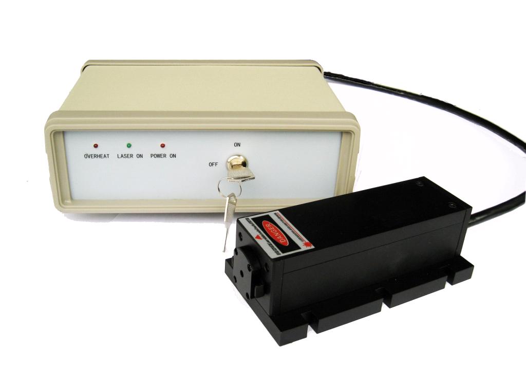
Coupletech Co., Ltd. Supply CW Laser models for medical instruments and scientific research, consists of UV laser GN-355, Low noise blue laser GL-473, Low noise green laser DL-532nm, Signal mode green laser CS-532, Sodium Yellow Laser GL-556, Light yellow laser GL-561, Orange yellow laser GL-593 and Infrared laser GL-1064, and these laser models cover a wide range of wavelengths: 355nm, 473nm, 532nm, 556nm, 561nm, 593nm, 1064nm, and son. The application of CW laser models is for Fluorescence stimulated for biological medical instruments, Interferometry, laser hologragh, flow cytometry, physical instruments, scientific research and so on. The average output power is 10 mW ~ 2000 mW, beam diameter at the aperture is ~ 1.5mm. Besides, single mode fiber coupled or customized is optional.


Diode Pumped CW,Diode Pumped Solid State Laser,Solid State Laser Diode
Coupletech Co., Ltd. , https://www.coupletech.com
