
3 Read the circuit diagram of ABS control system of Odyssey sedan
This article refers to the address: http://
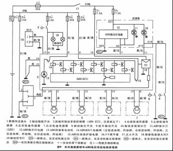
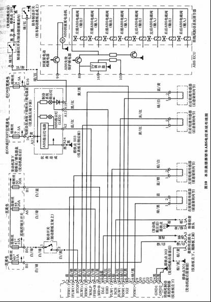
The circuit diagram of the ABS control system of the Odyssey sedan is shown in Figure 9, and the wiring diagram is shown in Figure 10. Among them, 8 solenoid valves are connected under the F48* fuse wire, and the return pump motor is connected to the fuse wire F41* through the F50* fuse wire, and the brake signal lamp 19 is connected to the F47* fuse wire. F46*, F47*, F48*, and F5o* are connected to the positive live wire of the battery (refer to "Automotive Appliances", 2004, Issue 9, P18).
The driver side fuses F4 and F9 must be turned on in the ON position. They are connected to the 5V power supply 16 and the instrument panel assembly in the ABSECU. It can be seen that the brake liquid level switch 8 and the parking brake switch 9 act on the brake system indicator light 10, and it can also be seen that the ABSECU acts on the brake system indicator light 10 and the ABS indicator light 11 respectively by the number 11 terminal. The black/red line and the blue/red line of the 7th terminal are controlled.
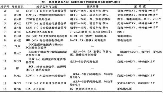
The terminal numbers of the four wheel speed sensors connected to ABSECU are: right front 18 and 2 terminals; left front 12 and 3 terminals; right rear 15 and 6 terminals; left rear 14 and 5 terminals, ABSECU terminal side test voltage The values ​​are shown in Table 1.
4 fault code reading method
In the self-diagnosis program, the reading of the fault code should be performed when the fault code exists in the ABSECU and the ABS indicator is still lit. If the ABS indicator is not lit, self-diagnosis may result in an error diagnosis.
a. Find the 2-pin maintenance check connector 18 (Fig. 9) under the driver's side dashboard. Connect the 2-pin plug terminal with the SCS maintenance check connector (07PAZ-0010100) or the jumper with fuse wire. The ignition switch is turned ON. , confirm that the brake pedal is not pressed.
b. When the ignition switch is in the ON position, the ABS indicator should be on for 2s, then off for 3.6s, then flash the first fault code. Do not count the above light and dark as a fault code. If there is no memory fault code in the ABSECU, the indicator will remain lit after 3.6 s is extinguished.
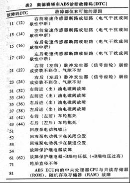
The indicator flashing method displays the fault code as shown in Figure 11. The fault location corresponding to the fault code and its possible causes are shown in Table 2.
c. Note: 1 The initial diagnosis is performed immediately after the engine is started until the ABS indicator is off. If there is a fault during the initial diagnosis, the fault codes 11, 31, 32, 33, 34, 35, 36, 37, 38, 53, 54, 81 may be stored. 2 Routine diagnosis (real-time diagnosis) is performed immediately after the initial diagnosis until the ignition switch is turned off. If there is a fault under routine diagnosis, all the above fault codes (except 54) may be stored. 3 Fault: Protection mode L: If a fault is detected, the ABSECU will store these fault codes. When the ignition switch is turned on, the fault will be detected. The ABSECU will shut down the entire ABS, the ABS indicator will light, and the brake system will return to the normal state. If the fault disappears, the ABSECU will turn on the ABS again and the ABS indicator will turn off. The fault codes that can be cleared in the L mode are 12, 13, 14, 16, 18, 21, 22, 23, 24, 41, 42, 43, 44, 51, 52, 53.
5 Fault code clearing
In order to clear the ABS fault code, these faults should be eliminated: after that, ensure that the car can not move, and the 2-pin check connector is not taken off from the 2-pin check socket SCSE. Note that the brake pedal should be operated according to the regulations during operation, otherwise it cannot Clear. It can also be done with the HONDAPGM detector.
a. Press the brake pedal and turn the ignition switch to the ON position. The ABS indicator should be on for 2 s and then off, then release the brake pedal. After 4s, the ABS indicator should light up again.
b. After the ABS indicator lights up, press the brake pedal again. After 4s, the ABS indicator will go out again, then release the brake pedal. After 4s, the ABS indicator should flash 2 times (0.3s), indicating that the fault code has been Cleared".
c. If the ABS indicator does not flash 2 times, repeat the above operation; if the indicator flashes 2 times and then continues to illuminate, the trouble code should be re-checked.
After clearing the fault code, disconnect the ignition switch and remove the jumper with fuse or SCS check maintenance connector (07PAZ0010100).
6 Odyssey sedan ABS troubleshooting example
Example 1: ABS indicator does not light up
a. The ignition switch is turned to the ON position and the ABS indicator should be on.
b. The ignition switch is turned back to the OFF position, and then turned to the ON position. The brake indicator light 1 should be on; otherwise, the repair of the two indicator power supply circuit breaks may be broken between the backup lamp fuse wire F9 and the instrument assembly. (Refer to Figure 9.)
c. Turn the ignition switch to the OFF position, disconnect the 25-pin connector of the ABSECU, and then turn the ignition switch to the ON position. If the ABs indicator is on, the indicator circuit is normal. Check if the 25-pin connector of the ABSECU is loose and replace if necessary. A good ABSECU module, check again, if the ABS light is still not lit, proceed down.
d. Turn off the ignition switch, remove the instrument assembly, disconnect the 30-pin plug of the instrument, and check whether the A2 terminal is connected to the ground. If it is turned on, repair the fault of the ABS control line and the body grounding; if it is not led to the next (see the instrument panel circuit, "Automotive Appliances", 2005, Issue 6, P17, P18).
e. Check if the No. 24 terminal of the 30-pin connector of the instrument assembly is connected to the body ground. If it is conducting, check whether the instrument assembly connector is loose (the A24 terminal is blank in the original vehicle data). If the connector is normal, replace the instrument. to make. Otherwise, the maintenance of the instrument assembly and the body grounding 6503 (behind the right side of the meter) open circuit failure, it may cause the ABS indicator circuit to work abnormally and not light.
Example 2: ABS indicator does not go out
Turn on the ignition switch (ON), the ABS indicator should be on for a few seconds and then turn off to normal. If it is lit at any other time, it indicates that the ABS has failed. If the ABS indicator is always on, it is not normal (see "Automotive Appliances", 2005, Issue 5, P13).
a. Check the fuse under the hood/ABS+B in the relay box, ie F48 (Figure 9). If the fuse is blown, replace the fuse and recheck whether the power supply circuit is short-circuited to the ground. If the circuit is normal, replace the ABSECU and try again.
b. Check the F9R/CMIRROR fuse in the fuse/relay box under the instrument panel (ie on the driver's side). If it is normal, replace it. If it is blown, check if the fuse circuit is short-circuited to the ground.
c. Disconnect the 25-pin plug of ABSECU to make the line out of the influence of ABSECU. Check the grounding voltage of terminal No.8, if it is the battery voltage, otherwise it should be repaired. F48*(ABS+B) fuse wire and ABSECU are disconnected. Where.
d. Turn the ignition switch ON position and measure whether the 25-pin connector No. 16 terminal is the battery voltage. If it is normal, otherwise check the disconnection between R/LMIRROR fuse F4 and ABSECU.
e. Turn off the ignition switch, check the No. 24 terminal of the ABSECU25 pin plug, and whether the grounding of the body is turned on, and the conduction is normal. Otherwise, the ABSECU is disconnected from the ground.
f. Turn the ignition switch ON, and short the 7th terminal (M9) of the 25-pin plug of ABSECU with the jumper to see if the ABS indicator is on. If it is bright, the ABS indicator on the instrument panel is normal. The problem may be loose in the 25-pin plug. If necessary, replace the test with a well-recognized ABSECU.
g. Short the A2 terminal of the 30-pin connector of the instrument assembly with the jumper. If the ABS light is on, check the disconnection between the instrument assembly and the ABSECU or the 30-pin plug of the instrument. If it is normal, change the instrument. The assembly is tried again.
Example 3 Fault Codes 11, 13, 15, 17: Wheel Speed ​​Sensor Line Open or Shorted
Note: If the DTC (DTC) is not cleared manually, the ABS indicator will not go out until the vehicle speed is below 10km/h.
a. Turn the ignition switch ON and the ABS lamp will not go out. Disconnect the 25-pin plug of the ABSECU, start the engine, and use a digital meter to measure the voltage between the grounding wires of the 18th, 3rd, 15th, and 5th terminals on the 25-pin plug (they are the right front wheel, the left front wheel, The high-speed end of the wheel speed sensor of the right rear wheel and the left rear wheel, as shown in Fig. 9), if it is not the battery voltage (normal), proceed downward. If it is the battery voltage, check if the harness between the 25-pin plug and the wheel speed sensor is short-circuited to the positive pole of the power supply.
b. Turn the ignition switch to the OFF position and check whether the terminals No. 18, No. 3, No. 15, and No. 5 are short-circuited to the ground. These four terminals are the signal wires of the wheel speed sensor. It is normal to not connect the iron. If the grounding iron can disconnect the 2-pin plug harness from the corresponding wheel speed sensor, check whether the wiring harness (+) and (1) terminals are grounded. If the grounding is turned on, the grounding of the wire harness between the ABSECU and the wheel speed sensor should be checked. Otherwise, the wheel speed sensor has a grounding.
c. The wheel speed sensor coil resistance should be between 400-2000 Ω (at 20 ° C). When the 2-pin plug is unplugged, it is measured between the two terminals (+) and (-) of the wheel speed sensor. If it is not unplugged, The corresponding terminal should be measured on the 25-pin plug of the ABSECU (terminal number is shown in Figure 9, Figure 10).
Right front wheel 18→2 fault code 11; left front wheel 3→12: fault code 13; right rear wheel 15→6: fault code 15; left rear wheel 5→17: fault code 17.
The air gap between the signal gear and the wheel speed sensor should be 0.4 to 1.0 mm, and there should be no chipping or looseness.
7 ASR and ESP
ASR (anti-schlitten regelung [de]) is the abbreviation of anti-skid drive system. Its function is to prevent the slip speed of the wheel from being controlled within a certain range when the car accelerates (rather than when braking), thus preventing the drive wheel from being fast. Sliding (the linear speed at which the wheel rotates is greater than the moving speed of the vehicle body). When the car is driving on a slippery road surface, the drive wheel does not slip when the ASR is not accelerating. If the car is driven later, it is easy to tail. If it is driven by the front, it is easy to lose control. With ASR, cars can alleviate this phenomenon as they accelerate. When turning, if the drive wheel slips, the whole vehicle will be deflected to one side, and equipped with ASR will make the vehicle turn along the correct route.
ESP (electronic stabilization program) is an electronic stabilization program that includes both ABS and ASR configurations. It is an extension of the functions of these two systems. Therefore, ESP is the highest form of current automotive anti-skid devices. The ESP system judges the running state of the vehicle through the signal of the sensor by the control unit, and then issues a control command.
Compared with cars with only ABS or ASR, the difference between ESP and ASR is that ABS or ASR can only react passively, while ESP can detect and analyze the vehicle condition and correct the driving error to prevent it from happening. ESP is particularly sensitive to oversteer or understeer. For example, if the car is slipping when turning left, it will turn to the right side of the tail. If the sensor feels slipping, it will send the signal to the ESPECU, so that the command can be quickly braked to the right. The wheel, which restores its adhesion, produces an opposite torque that keeps the car in the correct lane.
Geared Stepper Motor,Planet Gearbox,Spur Gearbox,Nema23 Geared Electric Motor
Changzhou Sherry International Trading Co., Ltd. , https://www.sherry-motor.com