
With the continuous growth of car ownership, the environmental pollution of automobile emissions has been paid more and more attention, and the continuous introduction of increasingly strict emission standards has made environmental protection an indicator that must be achieved by automobiles. In addition, as car consumption continues to mature, consumers are increasingly concerned about the inherent indicators of various functionalities of automobiles. As an alternative to the traditional Hydraulic Power Steering (HPS) and Electro-Hydraulic Power Steering (EHPS) technologies, Electric Power Steering (EPS) is gaining its advantages. It is used in more and more vehicles. Table 1 is the forecast of the consulting company Strategy Analytics for China's EPS market. We can clearly see this growing trend. It is expected that China's EPS market will grow at a compound annual growth rate of 16.9% during 2010-2017.
This article refers to the address: http://

This growing market trend is determined by the many advantages of the EPS system itself, which is mainly reflected in:
EPS can provide the best boost under various driving conditions, reduce the disturbance, improve the steering characteristics of the car, improve the steering stability of the car at high speed, and thus improve the active safety of the car.
The EPS only provides power when the steering is turned, thus reducing fuel consumption. Statistics show that EPS can save about 0.3 to 0.5 liters per 100 kilometers compared to HPS.
The EPS motor is powered by a battery, so it can provide power even when the engine is turned off or malfunctions.
The EPS eliminates the hydraulic structure and its parts are much smaller than the HPS, resulting in a lighter weight, a more compact structure, easier design and installation, and reduced noise.
The EPS is easy to adjust and detect, and can be quickly matched to different models by setting different programs, thus shortening the production and development cycle.
EPS does not have oil leakage problems, which can greatly reduce the warranty cost, reduce environmental pollution, and improve environmental protection.
EPS has better low temperature performance than HPS.
Auxiliary functions such as automatic parking system can be realized.
The increase in demand for EPS has also prompted many companies and research institutes to increase investment in research and development and production, which has led to the emergence of many new EPS system manufacturers entering the market. This phenomenon is particularly evident in emerging markets such as China and India. But these companies have a long history of producing EPS products, so a mature and reliable solution is especially important to them. The type, general structure and characteristics of the EPS system will be briefly introduced below.
Introduction to EPS
EPS is a system that provides auxiliary torque to the steering system directly through the power of the motor. It relies on the detection of engine, steering wheel, speed and other information to determine and provide the appropriate steering assistance, so that the steering process can be completed accurately, easily and safely.
Generally speaking, depending on the motor installation position and mechanical structure, the EPS system can be divided into: column-assisted, pinion-assisted, double-pinion-assisted, and rack-assisted. Figure 1 shows a brief description of the mechanical mechanisms, output torque and applicable models of various EPS systems.
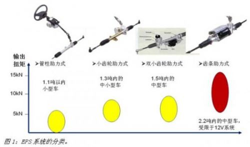
The column-assisted EPS system mounts the motor on the steering column and is connected to the steering shaft through a speed reduction mechanism. The characteristic is that the structure is compact, and the measured torque signal is in the same line as the steering wheel torque, thus controlling the response of the motor assist. Good performance, but the noise and vibration requirements of the motor are high. In addition, since the motor, ECU and speed reduction mechanism are arranged in the cockpit, the working environment of the motor and ECU is better, and the engine compartment is arranged. The pinion-assisted EPS system installs the assisting motor on the steering pinion and directly assists the pinion, so it can provide a larger boosting torque for a slightly larger model, but it will affect the assist control due to the existence of the universal joint. The accuracy of the features. The double pinion-assisted EPS system provides greater power than the pinion booster due to the addition of a pair of rack and pinion, but is also slightly more expensive. The rack-assisted EPS system can provide more power, but the whole system has complex structure and high cost, so it is suitable for luxury cars and commercial vehicles.
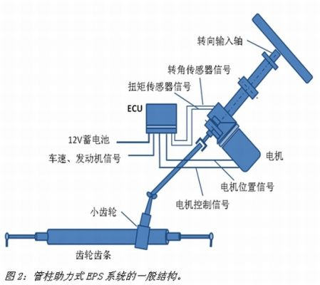
The working principle of each type of EPS system is basically the same. As shown in Fig. 2, usually an EPS system is mainly composed of a steering component, a sensor, a motor, a speed reduction mechanism, and an electronic control unit (ECU). When the driver turns, the sensor detects the torque and the angle of the steering wheel, converts it into a digital signal and transmits it to the electronic control unit. Based on these signals and the preset algorithm, the electronic control unit calculates the most suitable driving condition. The output torque and the signal drive the motor to work, and the torque output from the motor is assisted by the transmission system to the steering mechanism.
In order to make this steering process smooth, the EPS system needs to implement the following functions:
Power-assisted control: Provides a large assist torque during vehicle parking and low-speed driving, making the steering process fast and light, and providing a small auxiliary torque when the car is running at high speed to keep the steering process reliable and stable.
Correction control: Ensure that the positive moment of the car gradually increases during the process of turning from the straight state to the large angle. In addition, it ensures the straight-line driving performance of the car in the non-steering state, and prevents the car from returning to the positive or the overshooting when it is corrected at different speeds.
Damping control: Using the motor induced electromotive force to attenuate the steering wheel jitter phenomenon when the car is driving at high speed, eliminating the steering wheel shimmy caused by the unevenness of the steering wheel, and adding a certain damping to the steering process when the car is running at high speed, overcoming the steering and floating a feeling of.
Analyze and diagnose function: It should be able to monitor the running status in real time, and have fault alarm and prompt function. When the fault cannot be automatically eliminated, the EPS is turned off to make the vehicle enter the traditional mechanical steering mode.
Communication function: It should have the ability to communicate with other systems via CAN or LIN bus, and has an interface that can change the main parameters (mainly for motor control).
In order to achieve the above functions, the entire EPS system must work together efficiently and quickly. Therefore, the performance of the following components of the system is particularly important:
Sensor: The sensor provides the EPS system with all kinds of necessary information about the driving condition of the car. It is the sensory organ of the system, and its signal output should be as accurate, high-speed and simple as possible. EPS systems typically require signals from the steering wheel torque sensor, the angle sensor (optional), and the wheel speed sensor. At present, the general-purpose sensor adopts the analog signal processing mode, the signal output precision is not high, and the output signal needs further processing by the ECU, which increases the working load of the ECU, and the digital signal sensor reduces the occupation because it can give the digital signal directly available to the ECU. The ECU resources are used by more and more EPS systems to improve the accuracy of the signal.
Control strategy: The traditional steering system mainly provides steering assistance to the driver and reduces the steering burden. The EPS system also needs to solve problems such as excessive steering and returning during high-speed driving, which affects the stability and safety of the vehicle. Efficient and complete control strategy to ensure its performance.
Electronic Control Unit (ECU): With the continuous improvement of the EPS control strategy, the ECU's calculation and reaction capabilities are put forward higher requirements. As the core component of the EPS system, the ECU must have the ability to process sensor signals at high speed and high speed. Computational capabilities, ability to perform quickly and efficiently, ability to handle large currents, ability to communicate with other systems, system diagnostic monitoring, and fail-safe performance.
Power-assisted motor: Due to the uncertainty of the driver's steering, the power-assisted motor of the EPS system must be highly responsive and can perform the driver's steering intention in a very short time. Due to the limited installation space of the EPS system, the booster motor should also have high specific power, light weight and low noise. In addition, because EPS involves the safety application of automobiles, the power-assisted motor must be safe, reliable, and long-lived.
Mechanical structure: Compared with the traditional steering system, the EPS system adopts the worm gear reduction mechanism and has to withstand the huge torque of the motor output. Therefore, the mechanical structure of the system is required to have higher efficiency, better wear resistance and mechanical strength.
In response to these requirements of the EPS system, in order to reduce the difficulty of developing EPS systems for customers in the Asia Pacific region and shorten their development cycle, as the first agent of Infineon, Beijing Jingchuan Electronic Technology Development Co., Ltd. (Jingchuan Company) and Ying The company decided to use the successful experience developed by Infineon and the world's major EPS system suppliers for decades to develop an efficient and practical reference solution based on the actual situation in the region. Jingchuan and Infineon provide this solution to customers for reference and secondary development. In the following sections, we will introduce this scheme in detail.
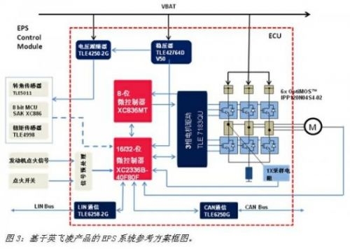
Automotive EPS solution based on Infineon products
As an inferior agent of Infineon, Jingchuan has strong technical capabilities, especially in the field of motor drive. The cooperation with Infineon is mainly based on Infineon's experience in working with the world's major EPS system suppliers, and in combination with Infineon's comprehensive product line, it has developed an EPS system that meets the needs of domestic and Asia-Pacific regions. Reference plan. Since the low-end EPS system using DC brush motor has a mature solution in the Asia-Pacific region, the reference scheme developed this time is mainly for the high-end permanent magnet synchronous motor solution, the motor power can reach 550 watts, the specific scheme The block diagram is shown in Figure 3. As can be seen from the figure, the whole scheme is divided into sensors, ECUs and motors. Below we will focus on the sensor and ECU sections.
1. sensor
In general, an EPS system employing passive positive control requires at least a steering wheel torque signal, a vehicle speed signal, an engine ignition signal, and an ignition switch signal. Since the solution is mainly for high-end applications, the active return control function is added, and thus the steering angle information of the steering wheel needs to be provided to the system.
At present, most EPS systems in China use a potentiometer-type torque sensor. The output is an analog signal, which must be further processed and occupy the A/D conversion port of the MCU to occupy the resources of the MCU. In this scenario we recommend the use of two Infineon linear Hall sensors TLE4998 as the torque sensor. The TLE4998 is an automotive-grade (-40°C-150°C) programmable linear Hall sensor with digital logic structure (20-bit digital signal processing) with digital temperature compensation. It can output SPC (Short PWM) as needed. Code), PWM or SENT (Single Edge Nibble Transmission) signals, where the PWM signal has a resolution of 12 bits, while the SPC and SENT signals have a resolution of up to 16 bits. In addition, TLE4998 also has various protection (anti-reverse, overvoltage, output short circuit, etc.) and online diagnostics (voltage, EEPROM error, etc.), and has strong resistance to stress and EMC.
In this scheme, we recommend the use of two Infineon TLE5011 to measure the phase difference to achieve steering wheel transfer measurement. The TLE5011 is a magnetic sensor designed by Infineon for GIR (Giant Magneto Resistance) technology for angle measurement. The sensor manufactured by this technology has the characteristics of high precision, small magnetic wheel gap, and a particularly compact sensor module due to the parallel placement of the sensor and the magnet. The TLE5011 can measure an angular range of 0-360°, directly output 16-bit sine/cosine values ​​using SPI signals, and its 3-wire SSC interface has a communication rate of up to 2 Mbps.
The vehicle speed signal required for the EPS system can be obtained by the wheel speed sensor in the ABS system, and the engine ignition signal and the ignition switch signal can also be directly obtained through the LIN bus.
In view of the fact that the TLE5011 outputs an SPI signal, we designed the torque sensor and the angle sensor in a module in the design, and used Infineon's 8-bit microcontroller XC886LM as the arithmetic unit to process the sensor model and directly Torque and angle information, because Infineon's XC88x family of processors contains a coprocessor called CORDIC, which is designed to calculate trigonometric, linear and hyperbolic functions with extremes for torque and angle calculations. High computational efficiency. The result of this module operation will be transmitted to the ECU master via the LIN bus.
2. Electronic control unit (ECU)
The ECU is responsible for handling sensor signals, executing control strategies, outputting control signals to drive motors, system monitoring diagnostics, and communication, and is a core component of the system. Since the scheme is to control the permanent magnet synchronous motor, the control algorithm needs to adopt the space vector control algorithm, so the calculation accuracy and speed of the controller are put forward higher requirements. In order to ensure that it can complete tasks accurately and efficiently, in this solution, we use Infineon's most advanced XC2000 series products as the main microcontroller. The XC2000 is a family of 16-bit microcontrollers based on 130nm technology designed by Infineon for automotive electronics and has the ability to execute certain 32-bit instructions. It uses Infineon's proven C166S-V2 architecture and is improved with a maximum clock frequency of 80MHz. The architecture uses multiple data bus technologies, most of which can be completed in one clock cycle and also supports DSP technology. The XC2000's powerful features and numerous peripherals make it easier for engineering developers to design their systems. The XC2000 series is divided into three sub-series, the XC2300 series is specially developed for safety applications, with responsiveness, high redundancy, high flexibility and stability.
The XC2336B used in this solution is Infineon's latest microcontroller, featuring a high-performance CPU with a five-stage pipeline up to 80MHz clock frequency and a Memory Protection Unit (MPU) that protects data from unauthorized access. It has different types of on-chip memory modules (8k stand-by RAM, 2k dual-port RAM, up to 16k data SRAM, up to 16k program/data SRAM and up to 320k program flash memory) and uses hardware CRC detection and ECC codes to discover Data errors and correct unit errors. Its numerous peripheral modules are flexible enough to meet a variety of needs, with two 9-bit synchronous A/D converters that can be expanded to 9 channels, 16 universal capture/compare units, and two PWM generations. The capture/compare unit, 5 timers, 40 general-purpose I/O interfaces, multi-channel CAN interface, etc., and can be debugged on-chip via DAP and JTAG interfaces. In addition, it comes with a watchdog and a crystal watchdog to keep the controller running. The chip is very compact and comes in a 64-pin green LQFP package with an energy-saving wake-up mode.
In addition to the main microcontroller, this solution also uses an Infineon 8-bit microcontroller XC836MT as a backup microcontroller. This is a microcontroller with an 8051 core. Its main function is to monitor the main microcontroller and cut off the EPS to make the car enter the mechanical steering state in case the main microcontroller fails, avoiding the car getting out of control and causing danger. .
In this scheme, as a power chip, a low dropout output regulator TLE42764D V50. Its output voltage is between 2.5V and 20V, adjustable or can be used as a 5V fixed output with 2% accuracy, and the output current is up to 400mA. It has a series of protections such as over temperature, reverse connection, short circuit, etc., and can be turned off by Enable to reduce the shutdown current to below 10μA.
To match the requirements of the sensor used in the system, the solution uses the voltage follower TLE4250-2G as the power source for the sensor. It has a low cost and can effectively prevent the short circuit of the sensor from impacting the microcontroller. The chip is available in a small SMD package. It has a wide input voltage range, can output a maximum current of 50 mA, and protects against over temperature, reverse connection, short circuit, etc.
For the most important motor control in the EPS system, we used Infineon's TLE7183QU, a special high-current three-phase motor driver chip to drive the permanent magnet synchronous motor in this solution. The TLE7183QU's three high-side and three low-side output stages control 6 to 12 external MOS transistors with a PWM wave of up to 30kHz with a 0-100% duty cycle. It has various protection and analysis functions such as overcurrent, overtemperature, and short circuit, and has two modes of shutdown and sleep. The entire product uses a 48-pin TQFP package with an external heat sink to ensure good thermal performance and soldering convenience. In order to accurately control the motor using the vector control algorithm, we use two sampling resistors to collect the two-phase current of the motor, and use the TTL7183QU's own one-way operational amplifier for overall current protection.
With the continuous promotion of high-end applications such as automatic parking systems, communication between EPS systems and other systems has become more and more tight. To meet the needs of inter-system communication, CAN transceiver TLE6250 (or TLE6251) and LIN are used in this solution. Transceiver TLE6258-2G. Among them, in addition to the ordinary functions of the CAN transceiver, the TLE6250 also has industry-leading electrostatic protection and electromagnetic interference resistance. The TLE6251 features extremely comprehensive fail-safe detection and very low sleep power. The TLE6258-2G is compatible with the 1.2, 1.3, and 2.0 LIN specifications and has low sleep power consumption.
In addition, in this scheme, we also use some passive devices of EPCOS to implement some auxiliary functions. Specifically, we use its electrolytic capacitor B41866C6107M000 and inductor T6174 as the filter circuit of the power supply to achieve the stability of the input power supply. The electrolytic capacitor B41695A7228Q007 is used as the ripple absorption capacitor of the power supply bus of the motor. In addition, the EPCOS thermistor B57702-M103-J is glued to the MOS tube to measure its temperature to prevent malfunction caused by overheating of the system.
From the perspective of the entire system, the chips used in this solution are designed for automotive applications, have an application temperature range of at least -40 to 125 ° C, and have strong electrostatic protection and electromagnetic interference resistance. In addition, most of these chips are made of lead-free materials and are environmentally friendly green chips.
This program is specifically developed for emerging markets in the Asia Pacific region, balancing performance, cost, development difficulty and other factors to adapt to the needs of customers in the region. From a global perspective, EPS systems are experiencing rapid growth, and some of the world's leading suppliers have introduced more advanced solutions, which we will briefly introduce below.
The development direction of the new EPS system
The development direction of the EPS system is miniaturization and high integration, so integrating the EPS controller into the EPS motor becomes a universal solution. Almost all of the world's leading EPS system suppliers have developed such a solution. The main feature is that all components are arranged in one or two ceramic plates in the form of bare chips, and the ceramic plates are placed in the back cover of the drive motor. Figure 4 is a schematic diagram of the structure of an integrated solution developed by Infineon for customers.
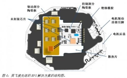
We can see that in this scheme all the chips are arranged on two ceramic plates, one on which all the power, the microcontroller and the MOS tube driver chip are placed, and the other one is placed on the MOS tube and An inductor and an enhanced thermal design. The advantages of this type of solution are obvious. The entire electronic control unit is integrated into the back cover of the motor, which is small in size and has few connecting lines. It fully utilizes the heat dissipation of the motor back cover and the system reliability is good. However, for customers in emerging markets in the Asia-Pacific region, because their terminal customer base is generally small and their technical strength is relatively weak, the implementation of the program is still very difficult, mainly in the following aspects:
The solution needs to be cooperated by the chip factory and the motor factory. The customization of the chip and the motor requires a large investment. This means that the majority of customers in the Asia Pacific region have high initial R&D expenditures, and there is no large customer base. In the case of support, the project risk is too great; due to the customization of the chip and the motor, the developer is required to have a strong system knowledge, and often involves the participation of the OEM, while most of the customers in the Asia Pacific region enter the industry. Soon, its own technology accumulation is not enough to participate in such a design; the program requires ceramic patch technology and die lead technology, and currently there are few patch factories in the Asia Pacific region that have such mature processing technology. .
It is with these factors in mind that the EPS solution based on Infineon products introduced in this paper is a practical and cost-effective solution.
Summary of this article
The use of EPS is becoming more and more extensive, especially in emerging markets in the Asia-Pacific region, where the total market and annual growth rate are becoming more and more eye-catching. The EPS technology solution based on Infineon products described in this paper has the advantages of comprehensive functions, reliable performance and high cost performance. It can help automotive system suppliers shorten the R&D process, reduce R&D costs, cut into the market at a faster rate and be convincing. The products occupy the market. As the first-class agent of Infineon, Jingchuan will work with Infineon to help customers achieve this ambitious goal.
At present, Lithium Polymer Battery is advanced rechargeable secondary battery. With cathode materia l- LiCoO2, LiMn2O ,Li(NiCoMn)O2, and anode material - C, lithium polymer battery has many merits: Good safety performance, high energy density, excellent charge retention, long cycle life, low self-discharge rate, low resistance, no memory effect and non-pollution.Lithium polymer battery is main applied for various customer electronic products, such as phone, smart security products, POS machine, GPS tracker and so on.
Lithium Polymer Battery
Lithium Polymer Battery,Mobile Battery,Rechargeable Lithium Polymer Batteries,Small Lithium Polymer Battery
Shenzhen Powercom Electronics Co., Ltd. , https://www.expowercome.com