
Impact speed control has been the most critical part of automotive crash testing. Many decisive indicators in the vehicle passive safety regulations, such as the human head injury index (HIC), chest composite acceleration, thigh force, etc., are closely related to the vehicle impact speed, so the impact speed must be strictly guaranteed. Within the range [1~4]. In the domestic rubber rope projectile collision speed control system, the design of the controller plays a decisive role in the performance of the entire control system. The MOTOROLA microcontroller system, which is widely used in the automotive industry, has excellent stability and a wide range of practical functions. The system is equipped with other auxiliary circuits to successfully construct the controller of the system. The experimental design proves that the designed controller can complete the speed acquisition and control algorithm implementation.
This article refers to the address: http://
1 Overall plan for vehicle speed control
In order to solve the time-varying characteristics of the rubber rope and the nonlinear characteristics of the driving device, and improve the ability of the whole system to resist the rolling resistance interference, according to the actual situation of the rubber rope ejection crash test system, combined with the actuality of the Tsinghua University automobile crash test room, the overall speed control The scheme is shown in Figure 1.
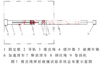
The "open loop" control is performed by controlling the length of the stretch of the rubber cord, and the speed is roughly controlled to a certain range. The speed "closed loop" control system is constructed by sensors, controllers and actuators mounted on the acceleration block, in an effort to accurately and stably control the speed of the vehicle during a collision.
For a car with a mass of 1.5 tons, the acceleration is released at a distance of 5 m from the end of the acceleration, and a speed of 15 km/h is obtained. From the kinetic energy theorem and the equivalent principle, the speed difference between the acceleration end and the acceleration end at a distance of 5 m from the acceleration end can be calculated:
![]()
Among them, v1, v22, and v21 are the vehicle speed obtained by stretching 5 m, the speed of the acceleration end when stretching 5 m or more, and the speed of stretching 5 m from the acceleration end. If in real vehicle collision v22+v21=100km/h
Substituting data can be obtained: v22-v21=2.25km/h
From the theoretical analysis and calculation results, it can be seen that the amount of change in the speed at the end of the acceleration is relatively small, which is beneficial to the control adjustment, but the time left for the control system is also small. The closed-loop system control strategy is to control the initial stage of the whole process without any control, and to adjust and control the speed to the end of the acceleration.
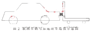
Figure 2 is a schematic illustration of the connection between the test vehicle and the trolley. Since there is only thrust between the pulley and the vehicle under test, its nonlinear characteristics and time-varying characteristics of the power increase the difficulty of the control system. The block diagram of the "closed loop" system implementation is shown in Figure 3.
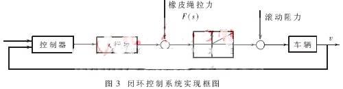
The actuator is a brake mechanism, which uses the kinetic energy of the rail and brake pads to reduce the speed of the acceleration pulley, which causes the acceleration pulley to disengage from the vehicle under test, thereby cutting off the power source of the vehicle under test and controlling the vehicle speed.
2 controller design and implementation
2.1 Overall design analysis
The controller requires the ability to have complex calculations, and the entire closed-loop system needs to be mounted on the acceleration block with poor working conditions. Therefore, the single chip microcomputer is selected as the core device of the whole controller, and the controller is built by the single chip system.
According to the requirements of the control unit, the microcontroller as the core device of the controller should have the following performance:
· There is enough RAM
· There is a large enough EEPROM
· A ROM that is large enough and easy to develop
·A/D conversion function
· Serial communication capability
· Strong enough interrupt function
· High stability, preferably with good impact resistance
According to the above performance requirements, choose MOTOROLA's MC68HC711E9[6] microcontroller.
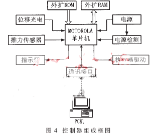
In order to achieve functions such as speed acquisition, status display, algorithm implementation and data processing, the block diagram of the designed controller is shown in Figure 4.
2.2 Measurement of speed
In the control system, the accuracy of the speed measurement directly affects the final control accuracy. If the traditional five-wheel method is used to measure the speed of the vehicle, the slip and the transmission hysteresis will make it difficult to increase the accuracy to the level required by the system. If the ultrasonic speed is applied, the measuring distance is for the 70m acceleration runway. Not enough. Therefore, the speed measurement scheme adopted is: the displacement acquisition is completed by the reflective photoelectric switch recording the equidistant light and dark stripes, and the time is recorded by the internal counter of the extended single chip microcomputer, and the final speed is calculated by the single chip microcomputer. This novel non-contact method for measuring large distances has high measurement accuracy, easy installation, and low cost.
As the controller of the speed control system, the measurement accuracy of time directly affects the accuracy of the control. The integrated clock with a precision of 30×10-6 provides a clock signal, and the time measurement accuracy is much higher than the speed measurement accuracy, so the error caused by the counter clock signal can be neglected. In addition, since each displacement collection point of the entire collision uses a 4-byte 32-bit counter to record the absolute value of time, the cumulative error is eliminated.
For the clock of the MCU counter, the selected division factor is 1 for accuracy reasons. The clock frequency of the counter of the single-chip microcomputer used for timing is the same as the frequency of the E clock signal of the single-chip microcomputer, and the clock period is 0.5 μs. For the 16-bit counter that the microcontroller itself has, in the case of the above clock cycle, the counter overflows every 32.77ms. The controller uses 4 bytes to record the time. The entire length of the system record is:
32.77×64=2097s≈35min
This length of time can meet the length of time required for the entire crash test process. In order to achieve the above design, for each shift point, the system uses two bytes to represent the overflow count of the 16-bit counter, which is the upper 16 bits of the 4-byte time value. The update of this value is implemented by the overflow interrupt program of the counter. . The other two bytes are the value of the 16-bit counter when the photoelectric switch passes through the light-dark stripe junction, which is the lower 16 bits of the 4-byte time value, which is implemented by the input capture interrupt routine. The input capture interrupt program stores the value of the 16-bit counter recorded by the input capture interrupt and the overflow count of the counter into the RAM corresponding to each shift point. To meet the accuracy requirements of time, the counter overflow interrupt has the highest priority among all interrupts, and the input capture interrupt has the lower priority.
In view of the consistency requirements of the time recorded by the counter during the test, it is undesirable to have interrupt nesting between the overflow interrupt of the counter and the input capture interrupt. The bar code used to set the displacement flag generates an interrupt signal with a spacing of 2 cm. For a test vehicle with a maximum speed of 60 km/h, the time difference between the two input capture interruptions is at least:
0.02÷60×3.6=0.0012s
During this time there are 1200/0.5=2400 E clocks, which can run an input capture interrupt routine and a counter overflow interrupt routine. Therefore, when the vehicle speed does not exceed the above vehicle speed, the MCU can successfully record the time.
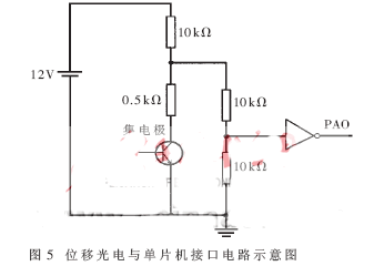
The output circuit of the photoelectric is in the form of an open collector interface. In order to connect with the CMOS input circuit of the single chip microcomputer, the input voltage characteristics of the voltage dividing resistor and the gate circuit are used for level conversion. The designed displacement acquisition and the circuit of the integer circuit are shown in Fig. 5. Show.
2.3 Other peripheral circuits
·Communication circuit
The MCU has a full-duplex serial communication interface, which can directly communicate with the computer. But the signal of the MCU is CMOS level, and the serial port of the computer is EIA-RS232C level, its level 1 is -3V~-25V, level 0 is +3V~+25V, so CMOS level and EIA are required. - Inter-conversion between RS232 levels. This system uses the chip MAX232 for level conversion. The serial communication mode is full duplex, the baud rate is 9600, 1 start bit, 8 data bits, and 1 stop bit.
In order to reduce the number of components in the control circuit, the MAX232 chip is designed on a separate communication board outside the controller. The communication circuit is connected to the controller and the host PC by two cables.
EIA-RS232C is a powerful universal serial communication bus. The MCU has only one output signal line, one input signal line and one ground line. Therefore, only some EIA-RS232C wiring is used. Request to send RTS and allow to send CTS short circuit, modem ready DSR and data terminal ready DTR short circuit, the corresponding sending data line is the same as the data receiving line of the single chip microcomputer, the receiving data line of the PC is connected with the transmitting data line of the single chip microcomputer, and the other two The land is common.
·The working mode and decoding circuit of the single chip microcomputer
In order to increase the amount of data collected by the system, 32K RAM is externally expanded, and the device selects HM62256. At the same time, in order to facilitate the design of the system and the design of the decoding circuit, the ROM of the external expansion also adopts the capacity of 32K, and the device selects 27C256, so that the B and C 8 bits each with a total of 16 bits of 64K addressing space. Since the B port of the MCU is the time bus and the data bus time division multiplexing, the 74HC373 is used to latch the address signal; the highest bit level of the address signal is used to distinguish the RAM and ROM address signals.
·Power circuit
The power supply uses the 12V battery commonly used in automobiles as the power supply voltage reference, which is beneficial to the energy supply of the drive circuit. Since many components on the controller operate at +5V, considering that the components used have both analog and digital circuits, if the same power supply is used, it will adversely affect the use of two voltage regulators. And 78L05, output +5V power supply voltage.
·Thrust acquisition circuit
Considering the characteristics of the microcontroller interface and the spectral characteristics of the signal, a resistor-capacitor low-pass filter circuit is added between the force sensor and the A/D pin.
·Signal feedback circuit
An output pin of the single chip is connected to the light emitting diode, and the flashing frequency of the light emitting diode is matched with a certain program to display the current state of the system.
·Test signal point
In order to facilitate the detection of the circuit, the output point of the important signal is set on the controller, which is beneficial to the debugging and analysis of the system.
·Drive circuit
The drive signal outputted by the single chip is amplified to enhance the load capacity and drive the solenoid valve of the brake device.
3 control algorithm and implementation
The simplest idea is that the brake is applied as long as the speed value exceeds the set value, and the acceleration pulley is separated from the vehicle to be tested by the braking force, so that the vehicle under test slides without power to the collision wall. The algorithm is simple to implement and clear in thinking, but the rolling resistance interference will not make the control effect and precision not high, and the uncertainty of the release position will make the guiding ability of the entire ejection system to the tested vehicle decrease. It can also be controlled by the well-established PID algorithm in engineering. Due to the rapidity requirements of the system, the integral link is excluded. The size of the PD coefficient can be specified during system commissioning, but the nonlinear mechanical properties of the rubber rope and the one-way force transfer characteristics of the acceleration pulley can greatly improve the PD algorithm. Decline [5].
In order to improve the precision of the control, the controller first realizes the prediction and compensation of the rolling resistance on the algorithm. The rolling resistance here is generalized and includes all resistances such as slope resistance, wind resistance and rolling resistance during motoring. The interference of rolling resistance is an important factor affecting the control accuracy of the system. If the controller can calculate and predict the rolling resistance, the control precision of the system will be greatly improved.
The force analysis of the vehicle under test is:
Mc×a=Ft-Fz
Where, Mc - the equivalent translational mass of the vehicle being tested;
a - the acceleration of the vehicle under test can be obtained by two differentials of displacement;
Ft—the force that drives the vehicle under test, which can be measured by the force sensor;
Fz - rolling resistance.
As can be seen from the above formula, the rolling resistance Fz can be calculated. In this way, the speed reduction rate of the tested vehicle after leaving the acceleration block in the unpowered state can be calculated, thereby increasing the set speed, the obtained speed will be more accurate, and the interference of the rolling resistance on the vehicle speed control is effectively suppressed. .
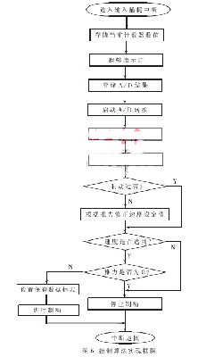
In order to solve the problem of nonlinear characteristics caused by the one-way connection between the acceleration block and the vehicle under test, the distance between the acceleration block and the vehicle to be tested should be limited during the acceleration process. The control algorithm stops the braking process when the thrust of the thrust sensor is zero during the braking process, and accelerates the acceleration pulley to contact with the vehicle under test. If the speed is still higher than the set speed, the brake is applied again, so that when the large speed closed loop requires power to accelerate the vehicle to be tested, the acceleration pulley accelerates the vehicle to be tested quickly due to the small distance from the measured vehicle. The effectiveness of the large closed-loop algorithm is guaranteed. The block diagram of the implementation of the algorithm is shown in Figure 6.
Correct Electronic Calculator advantage:
14 digits tax calculator,Check Calculator,We use good quality LCD display screen.fonts are clearly visible.Dual power solar power make life recycling.With the first raw material, fine workmanship and repeated testing, ABS is more durable and firm.

Correct Electronic Calculator
Correct Electronic Calculator,Correct Calculator,Correct Scientific Calculator,Check Correct Function Calculator
Dongguan City Leya Electronic Technology Co. Ltd , https://www.dgleya.com