
From the previous discussion of "How to Evaluate the Dynamic Efficiency of Class D Audio Power Amplifiers", if Poq represents the ratio of output power Po to static power consumption Pq, Emos represents the efficiency of the output power transistor and Eff represents the total efficiency, then the total efficiency:
This article refers to the address: http://
Eff = ( Poq x Emos ) / (Poq + Emos )
The above formula shows that the effect of Poq対 total efficiency is the same as the total efficiency of the output power transistor Emos対 efficiency, so the static power consumption Pq or the static current consumption Iq should be considered when evaluating the total efficiency.
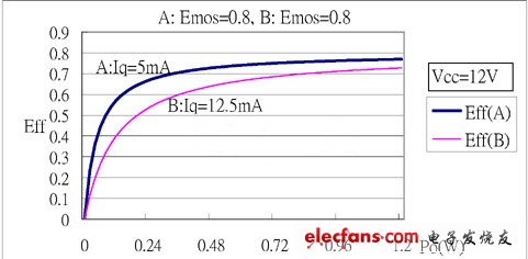
Figure 1
Figure 1 shows the Eff curves of two stereo Class D amplifiers. The power of these two amplifiers is 12V and the efficiency of the output transistors is 0.8. The quiescent current of the curve A amplifier is 10mA and the quiescent current of the curve B amplifier is 25mA. Since it is stereo, the quiescent current of each single channel is only half, that is, the curve A quiescent current is 5 mA and the curve B is 12.5 mA. It can be seen from the icon that the total efficiency of curve A is significantly better than curve B when the low output power or output power is about 10% of the maximum output power. Curve A is the Eff curve of the TMPA430DS at 12V and 8ohm resistive loads.
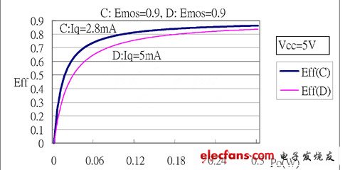
Figure II
Figure 2 shows the Eff curves of two stereo Class D amplifiers. The power of these two amplifiers is 5V and the efficiency of the output transistors is 0.9, the quiescent current of the curve C amplifier is 5.6mA and the quiescent current of the curve B amplifier is 10mA. So curve C has a quiescent current of 2.8 mA per channel and curve D is 5 mA. It can be seen from the icon that the advantages and disadvantages of the two curves are comparable to those of Figure 1. The low quiescent current has a high total efficiency Eff. Curve C is the Eff curve of the TMPA3155DS at 5V and 8ohm resistive loads.
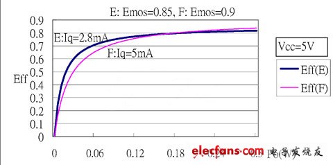
Figure III
Figure 3 also shows the Eff curve of two stereo Class D power amplifiers. The curve F is the same power amplifier as the curve D of Figure 2. The curve E and the curve C of Figure 2 are the same except that the transistor efficiency is only 0.85. Figure 3 shows curve E. Although the efficiency of the transistor is only 0.85 lower than 0.9 of the curve F, since the quiescent current of the curve E is 2.8 mA lower than the 5 mA of the curve F, the total efficiency of the curve E is lower than the output power less than 0.18 W. This emphasizes the effect of low quiescent current on the total efficiency Eff.
It is not necessary to consider the switching loss of the output transistor at the time of switching when evaluating the total efficiency. In the design of the Class D power amplifier IC, in order to avoid short-circuit current or through current when the output power transistor is switched, the output power transistor retains a dead zone when switching. Therefore, the NMOS of any one of the output terminals must be completely turned off before being turned on, and vice versa. Therefore, basically outputting the NMOS transistor does not cause switching loss. However, the output PMOS transistor charges the capacitance presented at the output during conduction, which includes the bonding pad capacitance in the IC, the drain capacitance of the output transistor, and other stray capacitance. This charged capacitor will discharge when the NMOS is turned on and the power consumed is already counted in the quiescent current or static loss. If both ends of the BTL are full nicknames, the quiescent current will not increase when the load is connected. If the quiescent current increases, the load has a capacitive component.
Due to the efficiency, the power will increase when the horn is heated, and the temperature will rise. The temperature rise will cause the output transistor Emos to deteriorate and the total efficiency will decrease. Therefore, it is suitable for high-power or low-efficiency power amplifiers. Heat dissipation is necessary. If the voltage benefit of the Class D amplifier is determined by the pre-circuit and not by the output, the output signal will be reduced as the temperature rises due to the output transistor conduction efficiency Emos. The output is reduced by the temperature. The transistor conduction efficiency Emos is determined by the size of the load. Since the on-resistance of the output transistor is increased, the output current is reduced, and the current of the power supply is also lowered. If the voltage benefit of the Class D amplifier is fed back from the output, the output transistor EMos deteriorates when the temperature rises. In order to maintain the voltage gain, the power amplifier maintains the output signal to generate more heat. Of course, the power supply The current also rises.
In order to reduce the electromagnetic interference (EMI) output, it is necessary to add magnetic beads (BEAD) filtering. The filter capacitor behind the magnetic bead usually uses 1nF, and the output PWM signal is charged and discharged once every cycle, with 5V power supply and 250KHz operating frequency. The quiescent current generated by each capacitor is
I = CVF = 1nF x 5V x 250K = 1.25mA
The stereo power amplifier of the BTL output has 4 outputs or 4 output filter capacitors, so the quiescent current is increased by 5 mA after EMI filtering. It can be seen from the above formula that the selection of a lower operating frequency power amplifier or a smaller filter capacitor can reduce the increase of quiescent current.
Class AB audio power amplifiers also have high efficiency at high output power, and the actual maximum efficiency is about 65%. Therefore, the efficiency of class D audio power amplifiers can be as high as 90%, but the power saved at the high power output is only relative to that of class AB power amplifiers. 25% of total power consumption. Even so, these two efficiencies do differ greatly in heat dissipation. If both power amplifiers consume 20W of energy, the Class D power amplifier outputs 18W of power and generates 2w of heat, but the Class AB power amplifier outputs 13W of power to generate 7w of heat. If the Class AB power amplifier is to output 18W of power, the heat generated is as high as possible. 9.6W. The 2W heat dissipation can be achieved by using a generally inexpensive package, but the heat of 9.6W consumes heat dissipation costs and space. In the use of the audio power amplifier is not always used at the maximum power, with a maximum output power of 3W class D audio power amplifier, if the output power is 0.5W or 1W, the efficiency is already higher than 86% or 88% according to the formula. For Class AB audio amplifiers with a maximum output power of 3W, if the output power is also 0.5W or 1W, the efficiency is only 25% and 37%. Therefore, the efficiency of class D power amplifiers and class AB power amplifiers is about 3 times. The lower the output power, the greater the difference in efficiency. The efficiency of class D power amplifiers is much better than that of class AB power amplifiers. If the audio content is a music signal, most of the time is at a low output power, and the class D power amplifier is much better than the class AB power amplifier. If the audio content is intermittent, such as a news broadcast, the intermittent time is relatively long. When the time is interrupted, only the static power is consumed, and the power amplifier with the same output is also indicated. The static power consumption of the class D power amplifier is only 10% - 20% of the AB class. The experimental data shows that when the Class D amplifier uses the battery to play music, the battery usage time is more than 5 times longer than the AB class.
The biggest disadvantage of Class D power amplifier is that it generates interference signals. Because the output signal of Class D power amplifier is a pulse wave with fast switching of large current, the interference signal is strong and the harmonic frequency of interference is wide, which is easy to cause poor reception of the receiver. The interference mode mainly comes from the wiring conduction or radiation. To avoid the wiring conduction, the magnetic beads and the filter capacitor can be connected in the wiring string to filter the high frequency harmonics. As for the low frequency harmonic interference, the LC output filter can be used, but the parasitic capacitance of the inductor is small. To avoid high frequency interference through the inductor. If the receiver and the power amplifier are placed on the same PC board, the power supply and the grounding are to be isolated. It is better to separately or individually supply power at the power supply end. As for radiated interference, the antenna end of the receiver and the output end or the trace of the power amplifier are placed on both sides of the PC board to increase the distance. The direction of the antenna arrangement is perpendicular to the output signal running line of the class D power amplifier to reduce the receiving efficiency of the antenna. To the lowest. The lead wire or speaker cable of the power amplifier output pin on the PC board is as short as possible and thicker as possible to reduce the antenna effect, that is, reduce the antenna radiation efficiency and reduce the electromagnetic radiation. If the mechanism design or stereo relationship needs to use a long speaker cable, the most effective way to prevent radiation is to use a speaker cable with an isolation line. The isolation line is grounded at the end of the PC board at the end of the speaker. Experiments confirm this shielding method. There is a considerable improvement in the use of the TMPA3155/3156. In addition, the proper placement of the larger volume of the metal-containing component can also shield some of the radiation signals. Since the interference signal is switched from the PWM, the lower operating frequency or PWM frequency can linearly reduce the interference energy. The operating frequency of Zhenyi's Class D amplifiers is mostly set at 250KHz except for special considerations. In addition to EMI considerations, the quiescent current caused by the previously mentioned EMI filter capacitors can be reduced.
Using patented modular design with thermal separation and thermal equilibrium, greatly improve the life time of the product.
No UV rays, environment friendly, high impact and shock resistance.
Prismatic shell designed, RGB power switch to White, Flashing RGB Dynamic light.
Automatically rotating, having the stage lighting effect.
Wide application to bars, disco, ballroom, KTV, home decoration, stage, club, party, etc.
Colorful light and white light two model switching mode switching time<1s.
Energy-saving, Efficiency> 92lm/W, Efficient driver >87%.
LED Party Bulb
LED Party Bulb,LED Dancing Bulb,LED Party Light,LED Party Dimming Bulb
Shenzhen Superlight Technology Co., Ltd. , https://www.superlighttech.com