
1 Introduction
In the interconnection scheme of the central air conditioning, elevator, ventilation, water supply and drainage, lighting, fire alarm and other subsystems in the intelligent building project, the serial communication mode of the modbus tcp protocol is adopted, which is fully compatible with the modbus industry standard, reliable data transmission, and fast response speed It is flexible to expand and realize the communication between each subsystem and the central management system through the Internet. The modbus tcp protocol is in the tcp / ip standard, and the application layer adopts the de facto standard modbus in the industrial field. Modbus uses port 502 of the tcp / ip application layer, which is internationally recognized. The serial bus mode supports rs-232, rs-422, rs-485 interfaces of various media. The network communication mode of modbus tcp adopts client / server mode, as shown in Figure 1.

Figure 1 Modbus tcp network communication mode
2 Modbus tcp serial communication analysis and implementation
Each subsystem in an intelligent building mainly uses plc as the main control module, as shown in Figure 2. The network interconnection adopts the modbus tcp network communication mode. The interconnection between the central management system and the network is an urgent problem to be solved. The PLC saves the relevant status and parameter information of each subsystem in the intelligent building in its registers, and the central management system needs to read The values ​​of some holding registers in plc are used for comprehensive monitoring and management of intelligent buildings. The modbus tcp protocol provides corresponding instructions to read the holding registers.

Figure 2 Schematic diagram of intelligent building system
2.1 Protocol analysis
Modbus tcp data message structure, as shown in Figure 3.

Figure 3 Modbus TCP data packet structure
A communication analysis of the modbus tcp read holding register (omitting the ip / tcp header): analyze the data message from left to right: 00 03 is the communication number. Generally, each communication will be required to add 1 to distinguish the difference The communication data message; 00 00 represents the protocol identifier, 00 00 is the modbus protocol; 00 06 is the data length, used to indicate the length of the next data, in bytes; 03 is the device address, used to identify the connection in the serial The address of the remote server on the line or network. The above seven bytes are also called the modbus message header. 03 is the function code. At this time, code 03 is to read the holding register data. 00 00 00 01 is the parameter of the function code, indicating the address and length of the holding register to be read. Analyze the data message from left to right: 00 03 is the communication number, the response message requirements are consistent with the previous corresponding request; 00 00 is the protocol identifier, 00 00 indicates the modbus protocol; 00 05 is the data length, use To indicate the length of the next data, in bytes; 03 is the device address, and the response message requirements are consistent with the previous corresponding requests. The above seven bytes are also the Modbus message header. 03 is a function code. Under normal circumstances, the response message requires to be consistent with the previous corresponding request. If an error occurs, it returns 80h + the previous function code. 02 is the first parameter of the function code, indicating the byte length of the next data; 00 17 is the data value in the holding register being read, that is, the value in the holding register with the address 00 00 required to be read is 0017h.
Test program (master) sends data (hex) and plc (modbus tcp slave) response data (hex) sample analysis is shown in Figure 4.
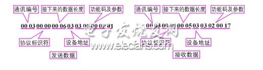
Figure 4 Sample analysis of program sending / receiving data packets
MC Flex Indoor Rental LED Display
Advantage of Indoor Rental LED Display P3.91 P4.81
1. Lightweight. Convenient in transporting and installing & saving labor cost, suitable for flow shows.
2. Nice appearance and simple structures.
3. Jointed correctly, being installed & dismounted by one person without tool.
4. Humanized operating interface with breakdown indicator lights, easy to maintain.
5. High debugging brightness and no damage to gray scale, achieving the debugging technology for nice image.
Indoor Rental LED Display
Indoor Rental LED Display,Indoor Rental LED Screen,Indoor Rental LED Screen Display,Indoor Stage Rental LED Display
Shenzhen Macion Optoelectronics Technology Co.,Ltd. , https://www.macion-led.com