
Portable electronic systems often require an external power source to charge their internal batteries through a wall adapter (AC-DC conversion subsystem). Most battery packs today use lithium technology because lithium technology can reduce the total weight of portable products.
But on the other hand, this product must comply with strict charging rules. It should be noted that if there is a problem in the charging step, the temperature of the lithium ion may increase, the heat may run out of control, and an explosion may occur, threatening people's lives. To avoid such accidents, one of the preferred safety measures is to protect the internal charger responsible for managing the charging of the battery pack from the outside.
The root cause of overpressure
In order to ensure that the charging voltage does not exceed the maximum rated voltage that the system can withstand, portable equipment and mobile equipment suppliers generally provide special wall adapters with the equipment. Using this type of adapter can ensure that the output voltage of the AC-DC converter is well controlled and the output ripple is well suppressed.
However, although the equipment supplier clearly recommends that users can only use original chargers, aftermarket accessories still have its market. For travel convenience, or only to ensure the continued use of the equipment after the original accessories break, users may use the second Or a third wall adapter.
Depending on the complexity of the adapter, its instantaneous output voltage may well exceed the rated voltage of the sensitive electronic devices used in the manufacture of these small portable products today.
Another possible reason for the increase in the output voltage of the wall adapter is the loss of the photocouple feedback (SMPS charger), which can occur even in the high-end AC-DC market. At this time, the output voltage may increase to 20V. If you use an overvoltage protection device (OVP), you can avoid directly facing such a dangerous voltage in the system.
Due to the series inductance in the adapter cable, hot swapping of the AD-DC converter may also cause overvoltage. The maximum ripple voltage at this time depends on the input capacitance of the mobile device and the parasitic inductance of the cable. If an OVP device is added to the mobile device, the soft-start feature of OVP will eliminate the overshoot effect caused by hot swap.
OVP design considerations
Unlike previous generations of overvoltage protection devices, in order to save PCB space, the new OVP now integrates bypass components (N MOSFET or P MOSFET). When calculating the PCB area of ​​a two-chip solution, the package size of the device and the wiring width between the two devices must be considered. The PCB space of the new generation OVP can save up to 60% compared with the old generation drive + MOSFET solution. However, considering the improvement of the heat dissipation caused by the charging current, the PCB layout must still be carefully designed. ON Semiconductor's data sheet document gives the Rθ curve of the thermal resistance from the solder joint to the air.
In addition, in order to reduce the temperature of the solder joints connected to the internal pads of the chip, additional copper surfaces must be added. Since the internal pad of this chip is connected to the drain of the NMOS, the additional copper surface added should be connected to the IN pin or to a separate plane, and this copper surface must never be grounded.
In addition, the definition of overvoltage threshold is also very important. The OVLO and UVLO thresholds are determined by the internal comparator. When overvoltage or undervoltage occurs, the internal comparator will cut off the bypass element.
The level set by OVLO must be higher than the maximum output operating voltage of AC-DC and lower than the maximum rated voltage of the first component of the system. Figure 1 shows the structure of a typical portable device based on a fully integrated OVP device (OVP here uses NCP347MTAE).
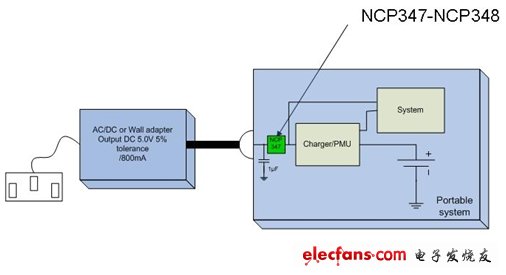
Figure 1: Structure of a typical portable device based on a fully integrated OVP device
To ensure the stability of the operation, an input capacitor must also be placed as close as possible to the IN pin in front of the device. The characteristics of the capacitor must be consistent with the characteristics of the protection device.
The first thing to check is the DC bias curve of the capacitor to ensure that the voltage it can withstand during operation is higher than the voltage range from UVLO to OVLO. For example, suppose you need a 1µF ceramic capacitor in front of the protection device.
Considering that the breakdown voltage of ceramic capacitors (above 200V) is higher than the maximum rated voltage of the protection device (30), a 10V / 1 µF or 16V / 1µF capacitor can be used on such products. The specific breakdown voltage of each capacitor depends on the quality of the ceramic material used. Figure 2 shows the DC bias and DC breakdown voltage of the 0603 / X5R / 1µF / 16V capacitor.
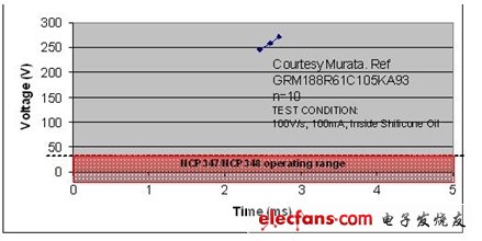
Figure 2: DC bias and DC breakdown voltage of ceramic capacitor 0603 / X5R / 1µF / 16V.
Main product features
Today, we can already achieve very low Rdson in a very small product package. For example, the NCP347 in a 2 & TImes; 2.5mm WDFN package has a Rdson of only 110mΩ, but it can withstand a DC current of up to 2 amps. The typical voltage drop between the wall adapter and the charger at room temperature of 25 ° C is 52mV. Because the loss is extremely small, such products can support low output voltage wall adapters. The smaller the pressure difference between the adapter and the charger, the less heat is dissipated by the portable device, and the greater the ability to withstand poor load regulation of the wall adapter.
The emergence of a new charger structure allows the internal switch to be quickly turned off with very low power consumption. Under normal circumstances, there will be no transient overvoltage in downstream systems. In the example mentioned above, the typical turn-off time is 1µs and the longest is only 5µs.
The new device may add an "enable" pin for starting the device or pulling it high when we want to isolate the system from the wall adapter to switch to battery-powered mode. In addition, you can also use a status pin to monitor the voltage value. When this pin is in the open-drain input state, it must be pulled up to the battery voltage through a minimum 10kΩ pull-up resistor.
If you connect the status pin to the input of a microcontroller and connect the "enable" pin to the output of the microcontroller, you can completely shut down the OVP device when the voltage on the device input pin continues to go wrong. And the microcontroller can turn on OVP at the right time according to the status of the status pin.
Design new solutions for new standards
IC manufacturers have provided novel solutions to solve overvoltage problems and effectively protect their devices, such as ON Semiconductor's NCP347 and NCP348. Because they can withstand 2 amps of charging current and provide protection up to 28V, and the shutdown speed is extremely fast, these fully integrated solutions can basically meet the requirements of most applications. In order to meet the requirements of different AC-DC output voltages, we provide some product versions with different OVLO thresholds. Their Rdson, turn-off time and power consumption can meet the most stringent requirements.
It is worth mentioning that one of the products is compatible with USB charging, which is particularly suitable for the new Chinese charging standard. In fact, more and more portable devices are now equipped with USB connectors, which can be connected to a host with a USB interface or a wall adapter through the USB connector to achieve charging.
Hifi Earbuds,Best Hifi Earbuds,Hifi In Ear Headphones,Best Hifi Earphones
Dongguang Vowsound Electronics Co., Ltd. , https://www.vowsound.com