
In order to realize the miniaturization of medical equipment and the wirelessization of medical monitoring, a medical monitoring system based on ZigBee wearable sensor is designed, which can expand the patient's activity space, reduce the workload of the guardian and reduce the medical expenses. The system adopts a two-layer structure of the ward/monitoring center, and uses the wearable sensor to collect physiological parameters such as body temperature and pulse of the patient. The data is processed and sent to the wireless communication module, and finally transmitted to the monitoring center by the ZigBee wireless network. The patient's physiological parameters were obtained experimentally and compared with traditional measurements. The results show that the system is stable and reliable, and the acquisition, transmission and display of physiological parameters of patients are well realized, which meets the design requirements.
0 Preface
With the development of science and technology, the medical and health industry has made great progress. However, most of the medical equipment in the hospital is still based on the traditional wired method. The wiring is complicated, the volume is heavy, the equipment is not easy to move, and it is not conducive to remote operation. . At the same time, many equipment probes attached to the patient's body will cause the patient's nervousness and psychological burden, which will cause a certain deviation between the test results and the real situation, affecting the accurate diagnosis of the disease. In view of the complicated wiring and single function of most medical equipments, this paper designs a wearable sensor monitoring system based on ZigBee technology. After the wearable sensor collects the physiological parameters of the patient, it is transmitted to the monitoring center by ZigBee network for further analysis by the staff. .
1 Introduction to ZigBee
ZigBee is a wireless communication technology whose protocol is based on the IEEE802.15.4 standard. The structure of the protocol from bottom to top is physical layer (PHY), media access control layer (MAC), transport layer (TL), network layer (NWK) and application layer (APL). At present, relatively mature short-range wireless communication technologies, including infrared (IRDA), Bluetooth (Bluetooth), Wi-Fi, etc., have their own advantages and application areas. However, for the medical monitoring field, ZigBee has no substitute. Its biggest advantage lies in the convenience of networking, the management of multiple network nodes, and the large scale of the network, which can fully meet the requirements for monitoring and management of several patients.
2 system structure
The monitoring system adopts a two-layer structure of the ward/monitoring center. The wearable sensors distributed in the ward use the sensitive components to collect the physiological parameters of the patient, send the data to the network coordinator through the ZigBee wireless network, and then the coordinator transmits the received data to and The connected upper computer, the system architecture is shown in Figure 1.
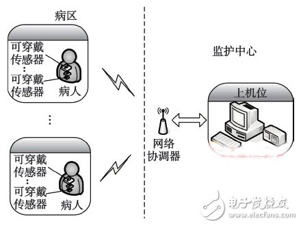
Figure 1 System Architecture
3 system hardware design
The system hardware is mainly composed of three parts: wireless sensor, network coordinator and host computer. The wireless sensor is responsible for collecting patient physiological parameters and data transmission; the network coordinator is responsible for data reception and communication with the upper computer; the upper computer is responsible for data display.
3.1 Wireless Sensor
As shown in Figure 2, the wireless sensor mainly includes a sensitive component, a data processing module, a wireless communication module, and a power module. The sensitive component is responsible for collecting the physiological parameters of the patient; the data processing module is responsible for pre-processing the acquired signal to meet the requirements of the input signal of the single-chip microcomputer; the wireless communication module is composed of 51 single-chip microcomputer and radio frequency chip, and is responsible for task assignment, scheduling and data integration of the entire sensor. With transmission and so on.
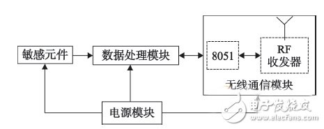
Figure 2 Wireless sensor structure
3.1.1 sensitive components and data processing modules
The system integrates a variety of medical monitoring sensors to measure body temperature, pulse, blood oxygen, blood pressure and other physiological parameters. Due to space limitations, this article takes the pulse as an example to illustrate the working principle and design method of the whole system. The basic principle of pulse measurement is: The translucency of human tissue (finger) changes periodically as the heart beats. When blood is delivered to human tissue, the translucency of the tissue is reduced; as the blood flows back to the heart, the translucency of the tissue increases. Therefore, the pulse acquisition module of the system irradiates the finger with infrared rays generated by the infrared emitting diode, and then uses the receiving transistor on the other side to capture the intensity of the light signal passing through the finger, and the reverse current of the receiving tube is linear with the light intensity of the transmitting tube. Relationship, which converts an optical signal into an electrical signal (current).
The sensitive components used in signal acquisition are the infrared emitting diode IR928-6C and its associated phototransistor PT928-6C, which features low operating voltage, high stability and high reliability. As shown in Figure 3, the current flowing through the diode is controlled to about 20 mA through the resistor R16, and is converted into a current (mA level) according to the received optical signal intensity, and converted into a voltage by the load resistor R17, and the human body pulse is about 50 to 200. Sub/min, the corresponding frequency is about 0.83 ~ 3.34 Hz, which belongs to the low frequency signal. R17 and C14 are used in the circuit to complete the task of filtering out high frequency interference.
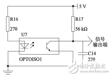
Figure 3 signal acquisition circuit
Since the human body electrical signal has the characteristics of high impedance, weak signal, low frequency and is in serious background noise, it is necessary to preprocess the electrical signal collected and converted, which is to ensure the maximum fidelity of the signal and facilitate subsequent Further data processing.
As shown in Figure 4, the data processing circuit includes signal filtering amplification and shaping.
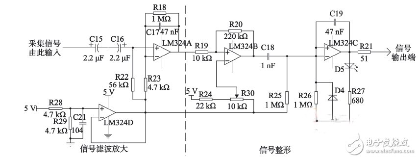
Figure 4 data processing circuit
In the filter amplification section, a simple optical isolation circuit is constructed by using C15 and C16 back-to-back series bipolar coupling capacitors to isolate the external interference light and design a low-pass filter composed of LM324A, R18 and C17. Cutoff frequency is approximately ![]() , can further remove high frequency interference signals. Since the pulse signal (voltage) of the acquired conversion is relatively small, generally at the mV level, the amplifier formed by R18 and R23 amplifies the acquired pulse signal by about 200 times, and has reached the V level.
, can further remove high frequency interference signals. Since the pulse signal (voltage) of the acquired conversion is relatively small, generally at the mV level, the amplifier formed by R18 and R23 amplifies the acquired pulse signal by about 200 times, and has reached the V level.
In the shaping process, the signal is converted into a square wave by the comparator LM324B. The R30 potentiometer can be used to set the threshold of the comparator within the operating voltage range of the system. Next, the square wave signal output from the pin of the LM324B is processed by a differential circuit composed of C19 and R25 to become a sharp pulse between positive and negative phases. The LM324D provides a reference voltage that passes through the LM324C and becomes the standard pulse pulse signal required by the system. Finally, the pulse signal is sent to the wireless communication module.
3.1.2 Wireless Communication Module
The wireless transmission module uses TI's highly integrated System on Chip (SOC) chip CC2530, which integrates a high-performance RF transceiver and an enhanced low-power 8051 microcontroller core. It has a long data transmission distance and strong anti-interference ability. As a basic chip, the 8051 is inexpensive, which greatly reduces the difficulty and cost of product development. At the same time, the software can be developed with C51 program code, which greatly shortens the product development cycle.
3.1.3 Power Module
The power module provides energy to the wearable sensor. Due to the volume limitation and the equipment cannot be replaced frequently, a series of effective measures must be taken to reduce the energy consumption to ensure that the medical node has strong endurance. The self-discharge rate of the lithium battery is low, and the discharge voltage is gentle, which meets the requirements of the system for the power supply, so the rechargeable lithium battery is used to supply the wearable sensor. However, when the system is working normally, the data processing module operates at 3.3 V and the sensor operates at 5 V. The power supply needs to be converted to voltage before being applied to the system. In the voltage conversion, the MC7805 is used to stabilize the output of 5 V, and the AMS1117 is used to stabilize the output of 3.3 V. As shown in Figure 5.
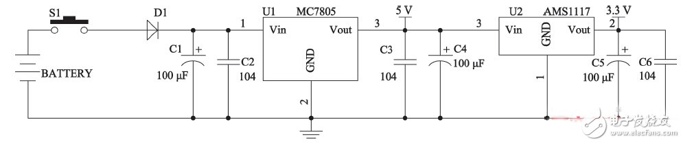
Figure 5 power module
3020 Smd LED supplier from China
Normally, the angle of those 3020 SMD LED is 120 degrees. We also can customize that angle as your needed, like 30 degrees, 45 degrees, 60 degrees, 90 degrees ect.
For 3020 SMD LED. They can be all kinds of wavelength's SMD LED, include the visible Light and the unvisible light.

In this catalog, we mainly introduce the 3020 SMD LED of visible light. 3020 SMD LED, size is 2.8*3.5mm. For this SMD LED, we can supply all kinds of visible wavelength and color on it. such as: purple LED, blue LED, cyan LED, lime LED, green LED, Yellow LED, Amber LED, Orange LED, red LED, deep red LED, red grow light LED , white LED, warm white LED, Pink LED and so on.
With 3020 SMD LED, we supply: purple 3020 SMD LED, blue 3020 SMD LED, cyan 3020 SMD LED, lime 3020 SMD LED, green 3020 SMD LED, yellow 3020 SMD LED, amber 3020 SMD LED, orange 3020 SMD LED, red 3020 SMD LED, deep red 3020 SMD LED, red grow light 3020 SMD LED , white 3020 SMD LED, warm white 3020 SMD LED, pink 3020 SMD LED and so on.
3020 Smd LED
Shenzhen Best LED Opto-electronic Co.,Ltd , https://www.bestsmd.com