
Power modules are favored by many engineers for their high integration, high reliability, and simplified design. However, even with the same modules, different usages can lead to different system reliability. Improper use can not only take advantage of the module, but also reduce system reliability.
1. Two-stage surge protection circuit, improper use is counterproductive
The power module is small in size. In the case of high EMC requirements, additional surge protection circuits are needed to improve system EMC performance. As shown in Figure 1, in order to improve the surge protection capability of the input stage, varistor and TVS tube are added at the periphery. However, the original purpose of circuits (a) and (b) in the figure is to achieve two levels of protection, but it may be counterproductive. If the varistor voltage and current capacity of MOV2 in (a) is lower than MOV1, in the case of strong interference, MOV2 may not be able to withstand the surge and cause damage in advance, resulting in paralysis of the entire system. Similarly, circuit (b), because TVS response speed is faster than MOV, often MOV is not working, and TVS is prematurely damaged.
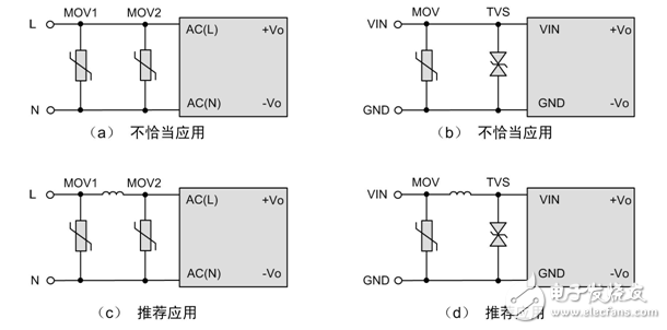
Figure 1 Two-level surge protection
Add an inductor to form a two-stage protection circuit. As shown in circuits (c) and (d), an inductor is connected in series to separate the protection device into two stages. For high-frequency surge pulses, the inductor has a large impedance, so the first function is the front-end varistor. The back-end pressure sensitive and TVS can further absorb the residual voltage protection module. In addition, even for single-stage protection, increasing the inductance can also play a role, avoiding the surge voltage directly applied to the module input.
2. The output filter capacitor is too large, causing the module to be abnormal.
It is generally recommended to add a certain filter capacitor at the output of the power module. However, in the course of use, excessive output filter capacitors are used due to insufficient understanding, which increases the cost and reduces the stability of the system.
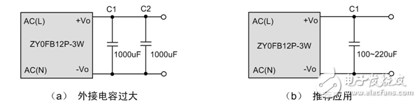
Figure 2 Capacitive load is too large
As shown in circuit (a) in Figure 2, a 3W module uses 2000uF capacitors for output. As you can see from the product manual, the module recommends a maximum output capacitance of 800uF. Excessive output capacitance can cause poor startup, while for micropower DC-DC modules without short-circuit protection, excessive output capacitance can even cause permanent damage to the module.
3. Connect the switching power supply chip, pay attention to the startup failure
As shown in Figure 3, the output voltage of the power module is gradually established. The LM2576 of the circuit (a) is not designed for undervoltage lockout. It starts when the VIN voltage is low. If the OUT load is too heavy, it may be misjudged by the 24V module. Too short or capacitive load is too large, resulting in poor start.

Figure 3 increases undervoltage lockout
Therefore, it is recommended to use the circuit (b), external simple undervoltage lockout, so that the output voltage of the 24V module is established to the preset value and then start the external switch power supply chip such as LM2576, which can largely avoid the problem of poor startup.
Alternatively, a power module with a larger power headroom can be used, and the ON/OFF pin can also be connected to the MCU for control.
4. Dual module, pay attention to load balancing
For dual output modules, the two outputs have different requirements on the load. These modules usually only provide voltage feedback for one of them, and the other is connected to the required voltage by transformer coupling.
When the voltage of the main circuit of the voltage regulator is too heavy and the auxiliary circuit is too light, the auxiliary circuit voltage will fluctuate more. When the auxiliary circuit has strict voltage requirements, a three-terminal regulator must be added. When the unregulated auxiliary road load is too heavy and the main path is too light, the output voltage may be unstable or the auxiliary circuit voltage may be too low. In this case, a dummy load is added to the main circuit.
Some modules of Zhiyuan Electronics are regulated by the main and auxiliary circuits. For example, ZY0GD1212DI3-15W is a dual 12V dual regulated output product.
5. Parallel and redundant, not the same thing
When there are two identical modules on hand, and the single power is insufficient, it is natural to think that the two modules are used in parallel to meet the power requirements. However, there is a great hidden danger in the method of using the power supply in parallel to increase the power, and the output voltage is biased. High modules require excessive current to cause excessive power to the module.
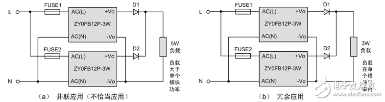
Figure 4 redundant application
As shown in the circuit (a) above, the load requires 5W of power, which exceeds the load capacity of a single module, and one of the modules may be overloaded. For this application, a single module with a power greater than 5W, such as ZY0JGB12P-10W, is required. The circuit (b) is not, the power of each module can meet the needs of the load, and this is a redundant design.
6. Although the tantalum capacitor is good, it should be cautious when placed on the power input and output.
é’½ Manganese dioxide capacitors are easier to break through short circuits, and have poor surge resistance. When starting up or when external power supply is connected, it is likely to generate large inrush current or voltage, causing burnout or overvoltage breakdown of tantalum capacitors. Ceramic capacitors or electrolytic capacitors are recommended without a rigorous evaluation.
Bed Elevator,Disable Elevator,Hospital Bed Elevator,Handicapped Elevator
XI'AN TYPICAL ELEVATOR CO., LTD , https://www.chinaxiantypical.com