
1 circuit category, implementation of main function description
The circuit shown in the figure below belongs to the voltage feedback circuit. When the output voltage changes, it is fed back to the control chip through this feedback circuit to adjust the output voltage and stabilize the output voltage. The circuit is as follows:
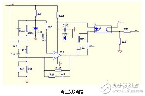
1.2 Analysis of working principle
When the output voltage changes, the voltage is divided by R27 and R28, and the voltage of the inverting input terminal of U15 changes. By comparing with the fixed voltage of the non-inverting input terminal of U15, the output voltage is amplified by the op amp, and the current through the photocoupler diode is passed. The change is transmitted to the output of the three-stage tube of the optocoupler, and then input to the control chip, and the control chip adjusts the output voltage to achieve stable output voltage.
2 Introduction to UC3842
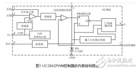
Figure 1 shows the internal structure of the UC3842 PWM controller. The internal reference circuit generates a +5V reference voltage as the internal power supply of the UC3842, which is attenuated by 2.5V as the reference for the error amplifier, and can be used as a power supply for the circuit output 5V/50mA. The oscillator generates a square wave oscillation. The oscillation frequency depends on the external timing component. The resistor R connected between the 4 pin and the 8 pin and the capacitor C connected between the 4 pin and the ground determine the oscillation frequency of the oscillator, f= 1.8/RC. The feedback voltage is connected to the inverting terminal of the error amplifier by the 2-pin. The 1-pin external RC network is used to change the closed-loop gain and frequency characteristics of the error amplifier. The square-wave output of the 6-pin output drive switch is the totem pole output. The 3 pin is the current detection terminal, which is used to detect the current of the switch tube. When the voltage of the 3 pin is ≥1V, the UC3842 turns off the output pulse to protect the switch tube from overcurrent damage. The UC3842PWM controller features an undervoltage lockout circuit with a turn-on threshold of 16V and a turn-off threshold of 10V. This is why it can effectively prevent oscillations when the circuit is operating near the threshold voltage.
2.1 UC3842 has the following characteristics:
1. The number of pins is small, the peripheral circuit is simple, and the price is low;
2. The voltage adjustment rate is very good;
3. The load adjustment rate is significantly improved;
4, the frequency response characteristics are good, the stability is large;
5, with overcurrent limit, overvoltage protection and undervoltage lockout.
2.2 UC3842 has a good linear adjustment rate
Because the change of the input voltage Vi immediately reacts to the change of the inductor current, it can change the output pulse width in the comparator without any error amplifier, and then increase the output voltage of the first stage to the control of the error amplifier, which can make the linear adjustment rate more Good; the load regulation can be significantly improved because the error amplifier can be used to control the change of the output voltage due to the load change, especially the amplitude of the voltage rise under light load is greatly reduced. The external circuit compensation network of the error amplifier is simplified, the stability is improved and the frequency response is improved, and the gain bandwidth product is larger. The current limiting circuit is simplified. Since the peak inductor current is induced on the resistor, the pulse-by-pulse limiting circuit can be naturally formed. As long as the level of Rs reaches 1V, the PWM is immediately turned off, and the peak inductor current sensing technique can be sensitively limited. The maximum current output.
3 UC3842 commonly used voltage feedback circuit
3.1 Output voltage direct voltage division as the input of the error amplifier
The output voltage Vo is divided by two resistors and used as a sampling signal, and is input to UC3842 pin 2 (inverting input terminal of the error amplifier). As shown in Figure 2.
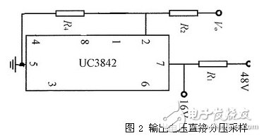
The advantage of this circuit is that the sampling circuit is simple, and the disadvantage is that the input voltage and the output voltage must be common ground and cannot be electrically isolated. It is bound to cause difficulties in power supply wiring, and the power supply operates in a high-frequency switching state, which easily causes electromagnetic interference, which inevitably brings difficulties in circuit design, so this method is rarely used.
3.2 Auxiliary power supply output voltage divider as an input to the error amplifier
The induced voltage generated on the auxiliary winding of the single-ended flyback transformer T rises as the output voltage rises. This voltage is rectified, filtered, and stabilized to obtain a DC voltage to power the UC3842. At the same time, the voltage is divided by two resistors and used as the sampling voltage, and is sent to the foot of the UC3842.
When the UC3842 is started, if the feedback winding does not provide enough UF, the circuit will start continuously and snoring will occur. In addition, according to experience, if UF is greater than 17.5V, it will cause abnormal operation of UC3842, resulting in a smaller output pulse duty ratio and lower output voltage. Therefore, the selection of the feedback winding turns and its winding is very important. Generally, it can be designed according to 13~15V. When the UC3842 works normally, the voltage of the 7-pin is maintained at about 13V.
The advantage of this circuit is that the sampling circuit is simple, and there is no electrical path between the secondary winding, the primary winding and the auxiliary winding, and the wiring is easy. The disadvantage is that the sampling voltage is not directly obtained from the secondary winding, and the voltage stabilization effect is not good. It is found in the experiment that when the load of the power supply changes greatly, the voltage regulation cannot be basically achieved. This circuit is suitable for situations with certain fixed loads.
Indoor Cable,Waterproof Pig-Tail Cable,PigTail Cable, Apl Moisture Barrier,Interconnect From Outdoor To Indoor
Shandong Qingguo Optical Fiber Co., Ltd. , https://www.qgfiber.com