
Sibas 32 is a special microcomputer control system developed by Siemens AG for the control of railway locomotives. It is called the siemens bahn automaTIsierungs system (Siemens Railway Automation System). The sibas 32 system takes into account the development perspective of the main functions of the drive control, and therefore places very strict requirements on the system. The sibas 32 system is a highly functional general-purpose computer system that can be connected to any device through standard and dedicated peripheral components and can basically complete all control and monitoring tasks for locomotives. The sibas 32 system can perform corresponding processing according to the driver's command, traction circuit status and response signals, and sends control signals to each contactor, Relay, solenoid valve, light emitting diode or digital tube, chopper and so on. The control unit can also perform a variety of monitoring functions, including diagnosis of its own functions and over-limit monitoring of external values. When the traction circuit exceeds the upper (or lower) limit set in advance in the program during operation, the system will perform corresponding processing according to the severity of the fault, automatically record this fault, generate corresponding protection and inform the driver. The biggest advantage of the sibas 32 system is that it is suitable for the control of various vehicles. Whether it is a phased rectifier, a chopper or an AC drive locomotive, it is possible to change the corresponding control simply by changing the hardware structure. The program thus realizes the control of the locomotive.
2 sibas 32 system featuresThe sibas 32 system implements the adjustment and logic control functions for the hxd1 locomotive, and it can display faults and perform related protection through the man-machine interface in a short period of time in the event of a failure in the test or operation. In the process of fault diagnosis of locomotives, the sibas expert 2 is used to analyze the hardware and software that cause the failure of the locomotive, improve the inspection efficiency and the accuracy of fault diagnosis; and the related signals can be detected and simulated by the monitor software in real time. Find the location of the fault and the cause of the fault, and accurately determine the faulty part of the locomotive. The sibas 32 system has the following features:
(1) The entire locomotive control system adopts a large-capacity signal processor module and dedicated software function integrated blocks and highly integrated circuits to ensure the reliable operation of the locomotive.
(2) sibas 32 system uses sibas g design language for logic design and processing. The design system supports the entire process from input and compilation to automatic documentation, resulting in a universally applicable system with a unified design entry and standards. Therefore, designing a new type of control system does not require changing a large number of hardware devices. It is only necessary to modify part of the software control logic to achieve design goals.
(3) In order to reduce the wiring of conventional locomotives and vehicles, there are sibas klip (sks1a, sks1b, sks3) devices (intelligent peripheral equipment connection terminals). With sibas klip, you can quickly and comprehensively control commands and information, and transmit the instructions to the central control unit in a timely and accurate manner using only a simple twisted pair cable as the transmission medium. The sibas klip station consists of programmable control devices (composed of cpu and simaTIc memory), input ports, and output ports. Thanks to its solid structure and easy disassembly, it can be freely and flexibly arranged on the locomotive.
(4) In order to expand the diagnostic capabilities already installed in the sibas 32 system, Siemens developed the sibas expert system (sibas expert 2). With this expert system, the auxiliary functions of the computer can be simply used to effectively analyze the data and contents stored in the diagnostic system. If necessary, the information query range can be expanded or reduced to quickly locate the fault.
(5) Intelligent operation and image display devices with an increasingly large capacity can realize high-capacity human-machine communication through a serial bus connection. The hxd1 locomotive uses a color LCD display. By expanding the capacity of the integrated computer of this display device, all the tools developed for the personal computer can be used to modify and supplement it; and the internal operating system adopts the Windows 32 system, which is more convenient to maintain.
(6) Not only shows the driver the required operating information, but also shows the actions that should be taken when the fault occurs. Maintenance personnel can use this interface to get further instructions for troubleshooting; at the same time, they can call up accurate space layouts that represent the parts to be controlled or replaced, and give additional instructions.
It can be seen that the sibas 32 system will be used more extensively than any kind of locomotive train control system.
3 sibas 32 system structureSibas 32 system structure is simple, using distributed control mode, composed of ccu, tcu, mmi and sks1 (sks1a, sks1b), sks3, locotrol, etc. The control block diagram of sibas 32 applied to hxd1 locomotives is shown in Figure 1.
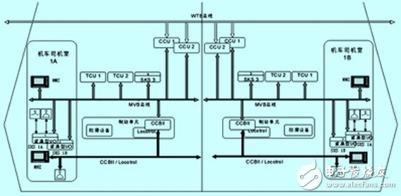
Figure 1 hxd1 locomotive control block diagram
As can be seen from the figure, sks1, ccu, tcu, etc. are redundant. Through the train bus, a maximum of two (4) locomotives can be reconnected, and locotrol can realize the wireless reconnection of 4 (8) locomotives. This provides a reliable technical guarantee for the heavy-duty transport of 10,000 tons for the Daqin Line. .
3.1 Central control unit ccu (central control unit type 3)
The ccu is the core unit of the entire system. The locomotive control, regulation and monitoring are implemented and controlled by ccu. The ccu of the hxd1 locomotive is a type 3 32-bit microprocessor consisting of a gateway gateway, a CPU cpu, a mvb32-4, and a power supply. It can realize the reconnection of two (4) locomotives. Ccu uses a redundant design, each car has 2 ccu, one main ccu, the other is from the ccu, the structure is exactly the same function, after a fault the other can continue to work, does not affect the normal operation of the locomotive.
The main function of ccu is to store the locomotive parameters for this section, record the locomotive events in this section, display the event of the reconnected car, detect the entire vehicle, read or dump the data through the rs232 interface, and input the system software uploaded by the locomotive central control unit. port.
3.2 traction control unit tcu (tracTIon control unit)
Tcu is the core control unit of locomotive traction and consists of a central processor module, a memory module, a chopper control module, a digital interface module, a digital input/output module, an analog interface module, a control system detection module, and a train control signal input conversion module. Digital signal input conversion module, contactor driver module, igbt trigger module, starting unit and other components. Its role is to control and regulate the traction and regenerative braking of locomotives, to achieve electrical anti-idling/sliding protection, and to achieve the functions of open and closed loop control, speed and frequency synchronization, fault handling and monitoring.
3.3 intelligent terminal interface unit sks1a, sks1b, sks3 (sibas kilp)
Sks1a, sks1b, sks3 are intelligent peripheral device connection terminals, sks1a, sks1b is a compact design of the digital input / output interface, specifically for the driver's room, it converts the driver control instructions into digital signals, and transmits the signal to the ccu; The sks3 uses decentralized input/output to reduce the wiring required in the vehicle and increase control and diagnostic capabilities.
3.4 Monitor mmi
Each cab has a display mmi containing a microcomputer processing unit. MMi provides locomotive information status, fault information, and measures taken and information settings, can be converted in Chinese and English, the operating system is windows32 system, the user interface using windows graphical interface. Mmi communicates with ccu through an mvb interface, using a laptop to modify the display time, locomotive number, and other parameters of the locomotive.
3.5 Train communication network tcn (train communicaTIon network)
The train communication network (tcn) includes two parts of the train bus (wtb) and the multi-purpose vehicle bus (mvb). With redundant design, one-way failure occurs and data can be exchanged on the other side. Wtb is responsible for the external communications between locomotives a and b and the engine shop, while mvb is responsible for the internal communication of single locomotives.
Tcn network physical layer consists of copper twisted pair, data transmission rate of 1mbit/s. The wtb bus is 850m long and the mvb bus is up to 200m long. In order to improve the reliability of tcn bus system, tcn bus adopts system-wide redundant design technology. Each train bus node has four interfaces; each single bus node has an ordinary interface and a redundant interface, each interface connects the previous node and the next node; each bus cable is laid from one node to another node and at each Closed loops are formed at the bus nodes. In the bus terminal node, it is connected to the matching resistor through the relay on the gateway.
4 sibas 32 graphical principle design software sibas gOne of the most prominent features of the sibas 32 system is its full graphic design. The sibas g language is used as a development and design tool. It uses a simple tool to effectively support the entire design process, and the graphic design is displayed on the screen. Designers can use the functional integration block of the sibas g library to call the smallest integrated block to form the entire device's software. It is positioned on the functional map with the mouse, and is connected to each other through simple inputs and outputs; the integrated block and signal names are determined by the designer according to the design requirements. Therefore, when designing, using, repairing, and changing, the user can use this tool without having the relevant expertise, and can perform the technical processing as with the conventional block diagram. More importantly, designers do not have to consider the technical conditions of all data related to the actual processing program in the computer. The entire function of the sibas 32 system is represented and processed in several different levels: control program → function package → functional components → image electronic amplification. The lowest level is the function integration block. Several integrated blocks can synthesize a functional component, several functional packages are composed of several functional components, and finally all the functional packages constitute a complete program. Due to the expansion from the outside to the inside and the electronic magnification of the image, when working with this system, the sub-functions that you want to change can be directly accessed. In addition, the finest part can be processed with the maximum resolution, while in other cases it can also be used with an explicit dense representation.
The graphic design can be automatically compiled in the computer with the required code and tested at the same time. However, many checks cannot be performed at the time of the input of the function chart, so it is then necessary to use a testable format of a runnable computer program. The sibas g's structure is manually operated and designed entirely for documentation. It automatically provides documentation for control functions while designing, so always uses real-time data for work. The continuous density of documents in such computer programs and documents has made major advancements in quality (and it can be done without negligence) and time-consuming (work data is always real-time data). Therefore, the screen display exactly matches the file display.
The function block itself is written in the c programming language. It is because of the application of this high-level language that the sibas g itself has nothing to do with the target processor, so it can simply replace the new processor. It is worth mentioning that the program generated by sibas g is processor-dependent and must be replaced when changing the processor model. This ensures that the hardware can also be improved in the future without having to develop software that is very risky and that it does not increase excessive development costs.
As can be seen from Figure 2, the left side is the project list (48 projects for version 7.00), the middle is a detailed list, and the right side is the detailed logic control schematic. It can also be seen from the figure that the ccu control software is controlled by the related signals through logic relations, and the related logic can be tested by the monitor software so as to speed up the judgment of the speed of failure; it can also modify the related signals. Perform a simulation of the fault to achieve the reproduction of the fault. Due to the technology transfer, the software design for ccu has been delivered to Zhuzhou Electric Locomotive Co., Ltd. This article does not elaborate.
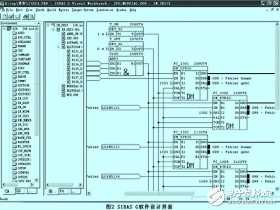
Figure 2 sibas g software design interface
5 Application of diagnostic software (sibas expert 2)After the locomotive enters the maintenance section, the maintenance personnel use the sibas expert com program on the laptop computer to download locomotives a and b data through the rs232 port and send the data to the segment LAN server. In this way, technicians can use sibas expert 2 (client) software for analysis. The sibas expert 2 software is a 32-bit application that can run under windows 2000, windows xp, and is currently not suitable for use on windows vista. According to the requirements of Chinese users, Siemens has finished the software and is very easy to use.
5.1 Installation of Diagnostic Software
Users use the cd installation disk and installation method provided by Siemens to install the sibas expert 2 program. Since Siemens conducts technical confidentiality and protects the locomotive setting data, the user uses the customer's version. However, through the transfer of technology and other technical means, the relevant user rights are currently basically owned. Although the actual functions of the software are not subject to the relevant restrictions, Siemens' detailed data on tcu is downloaded and analyzed by the dsp software. At present, China has no relevant software and is trying to develop the process. 5.2 Analyzing Data and Finding Faults
(1) Analyze the data. First, open sibas expert 2.exe in the program bar and click ![]() Import locomotive data that needs to be diagnosed. Then, in the sibas expert 2 interface, click
Import locomotive data that needs to be diagnosed. Then, in the sibas expert 2 interface, click ![]() Start an ordinary form, you can see a detailed record of ccu and tcu events. How to quickly determine the fault location by analyzing the ccu and tcu event records? The following takes the fault of locomotive b locomotive of hxd1 0077 locomotive as an example to discuss the method of finding the fault of hxd1 locomotive.
Start an ordinary form, you can see a detailed record of ccu and tcu events. How to quickly determine the fault location by analyzing the ccu and tcu event records? The following takes the fault of locomotive b locomotive of hxd1 0077 locomotive as an example to discuss the method of finding the fault of hxd1 locomotive.
For example: On September 5, 2008, the hxd1 0077 locomotive appeared several times because of the tcu reason to jump and break. Through the analysis of downloaded data, it was found that within a few seconds, 34 kinds of faults occurred at the same time because of code 85. The "earth fault detected" fault occurred at the earliest, and at the same time, the fault code was detected as 86 "earthing fault detected in the inverter", so the inverter was switched off and the automatic switch of tcu2 was disconnected for a short time.
(2) Find the fault. Since the ground fault detection of the main inverter is judged by the ratio between the output voltage of the intermediate DC link voltage sensor and the output voltage of the grounding link voltage sensor, it can be determined that the fault may be the following according to the fault codes 85 and 86. Several kinds:
There is indeed a ground fault, that is, the 3rd and the 4th motor grounding and the main inverse inverter module to the 3rd and 4th motor wiring ground; detection circuit failure, ie, the grounding resistance is not correct or the ground voltage sensor is faulty; A fault occurs, that is, the voltage sensor input board (l095) of tcu2 or the main inverter voltage control and monitoring board (g019) fails.
The on-site pass test signals $zfqmd and $tcntqmd are normal (frequency code 3, delay 600). Therefore, there is no problem to determine the tcu hardware, that is to say the third type of failure does not exist, the test motor is not grounded. The two-section locomotive's grounding resistance and grounding voltage sensor were adjusted to perform locomotive high and low pressure tests. The locomotive re-emerged with the same fault. Then the fault should be the main inverse inverter module to the third and fourth motor wiring. By hoisting the auxiliary transformer, it was found that the 3rd and 4th motor terminal posts of the locomotive were burned and grounded, and the motor terminal was burned. After the equipment was replaced, the locomotive operated normally.
6 ConclusionWith the development of AC drive control technology in China, the on-site application unit must continuously research the sibas 32 microcomputer control system in order to gradually realize localization so as to achieve the purpose of introducing, absorbing, digesting, and recreating new technologies. In addition, with the extensive use of AC locomotives in China, the on-site use units will increasingly rely on analysis software to analyze and deal with problems, which is a good reference for the design and manufacture of domestic locomotives in China.
Relay
Solid State Relay,Relayrelay Electrical,Motor Overload Relay,Dc Coil Contactor
NanJing QUANNING electric Co.,Ltd , https://www.quanningtrading.com