
0 Preface
The spatial orientation tester is a widely used electronic measuring instrument. Especially with the development of microelectronic technology, the application of the spatial orientation tester in the navigation field of vehicles, ships and aircraft is becoming more and more mature. The spatial orientation testing technology studied in this paper is mainly based on MSP430 microcontroller. Because the MSP430 family of microcontrollers is a 16-bit ultra-low-power, reduced-signal (RISC) mixed-signal processor that can be used to simulate multiple circuits, digital circuits, and microprocessors for different applications. Integrated on a single chip. Therefore, the author has studied how to use MSP430 microcontroller to control the interface circuit of each module, and it can be well applied to actual measurement.
1 Space orientation test design of each hardware interface
This paper mainly studies the spatial orientation tester based on MSP430 MCU. The working principle of this instrument is to transmit the data received by the position information receiver to the readable memory of the MSP430 MCU, and then display it on the LCD screen through the output. In this process, we need to design a hardware interface circuit to connect the information receiver and the liquid crystal display, while the read and write control of the MSP430 microcontroller needs to be done through language programming.
The basic idea of ​​the space orientation tester based on MSP430 MCU is to use the MSP430 MCU to control the functions of the space orientation tester with the advantages of convenient operation, simple interface, small size, low energy consumption and low cost. Since the information receiving module interface circuit of the spatial orientation tester is few, but the application range is very wide, it is necessary to design a multi-interface circuit to connect the display, the single chip and the like. In addition, in order to improve the data processing and application capabilities of the spatial orientation tester, serial communication between the PC and the spatial orientation tester is required. Achieve good human-machine dialogue, simple operation and friendly interface, humanized input and display capabilities. Therefore, its hardware interface module design is shown in Figure 1.
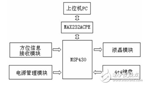
Figure 1 hardware interface module
The MSP430 MCU is the core part of the spatial orientation tester. It can not only coordinate the internal software modules of the whole instrument, but also sort and sort the collected data information and calculate the corresponding values. The accelerometer is primarily based on the ADXL203, a complete high-precision, low-power, single-axis/two-axis accelerometer that provides signal-conditioned voltage output, all integrated into a single-chip IC. With a full-scale acceleration measurement range of ±1.7 g, these devices measure both dynamic and static accelerations. The whole signal circuit of the spatial orientation tester based on MSP430 MCU is to amplify and filter the output signal of the sensor. The crystal frequency of the circuit is 411.0592MHz and the baud rate is 4800. The initial value of the baud rate is set to FFFAH. The database is mainly composed of AT24C16 memory, its low voltage and standard voltage is Vcc=1.8V-5.5V, with 2048&TImes; 8 (4k) storage space, 2-wire serial bus, Schmitt trigger, noise suppression filter input. Bi-direction transmission protocol, 100kHz (1.8V, 2.5V, 2.7V) and 400kHz (5V) compatible transmission rates. Hardware data write protection pin, 8-bit page write mode, allows partial page write operation, device internal write cycle up to 10ms, high reliability, 10,000 write cycles, 100 years of save time. In the LCD display, it mainly depends on the serial/parallel data receiving mode of the LCD. If it is low, it is in serial mode. If it is high, it uses parallel mode. In addition, the liquid crystal display is designed to be center-symmetric and can be positive and negative. Display, easy to read values. The keyboard part uses a 16-keyboard, 4 & TImes; 4 array, the column line is drawn from the lower 4 bits of the PB port, the lower four bits of the PC lead the line, and then the +5V voltage is connected through the resistor. The power button of the keyboard is responsible for the control of the switch. The display mode selection button is used to control the spatial orientation information of the tester. The measurement mode selection button is used to switch the orientation measurement in different situations. The hold button is read by keeping the measurement on the display. In order to reduce the power consumption of the spatial orientation tester, the MSP430 MCU can increase the high level according to the actual situation and issue the keyboard scan signal. In other cases, the low level can be used.
The serial input port and the serial output port of the spatial orientation tester based on the MSP430 MCU are respectively connected to the MSP430 MCU, and are mainly responsible for receiving various information transmitted by the position information receiver. The MSP430 microcontroller-based spatial orientation tester has a supply voltage range of 1.8 to 3.0V. The tester's hardware platform requires three voltages. The core operates at 1.8V and the memory and external I/O devices operate at 3.3V. The operating voltage of the system platform is 4.2V. The instrument uses a wide-level output, multi-level output through the converter, and a stable voltage can be obtained by the LM317 regulator. In addition, the design of the reset circuit is also a very important part. The reset circuit mainly completes the power-on reset of the tester and the user's key reset function during the running of the tester. The reset circuit is mainly composed of a simple RC reset circuit and has a reliable logic reset function. In order to ensure that the tester can be effectively reset, it is necessary to select the appropriate parameters and adjust the reset state time. For the S3C2410X, the nRESET terminal must be held low for at least 4 MCLK cycles after the tester is powered up. The two-stage non-gate circuit is used for button debounce and waveform shaping; the output state of the nRESET terminal is opposite to the Reset terminal for high power. Flat reset.
2 Software design of each interface of spatial orientation test
The software working platform of the spatial orientation tester based on MSP430 MCU mainly includes embedded editor, compiler, assembler, connector, debugger and function library manager. The programming of the spatial orientation tester based on MSP430 MCU can be divided into three parts: the traditional communication program design of the data input of the orientation information receiver, the programming of the LCD data display output, and the serial communication module program of the lower computer.
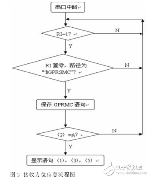
2.1 Receive orientation information flow design
The process of receiving orientation information is shown in Figure 2 below. First, a serial port interrupt needs to be set. The serial control register RI indicates the flag for receiving the interrupt. When RI=1, the spatial orientation tester receives the data. Then RI to zero to determine the information status of the next set of data. Enter the path letter into the buffer to determine whether the statement is A (current data). If it is judged as A, the required statement will be output to the LCD display. If it is V (voltage data), it will not be displayed.
ONEREEL cable drum rollers are an ideal labour and effort saving device for installating cables durining electrical installations. Making light work of handling and decoiling cables from cable drums.
cable drum roller,cable drum dispenser,cable drum holder,cable drum de-reeler
NINGBO BEILUN TIAOYUE MACHINE CO., LTD. , https://www.spool-manufacturer.com