
With the development of LED technology, LED lighting has become more and more widely used in landscape lighting, plaque lighting and large-screen displays due to its long life, low power consumption and controllable color. And development potential, this article introduces an LED lighting driver that can easily control the light intensity and color of the LED. It can be programmed to control multiple LED patterns, and the system can communicate with the computer through the serial port to display the upper position. Information transmitted by the machine.
1 LED dimming principle
At present, there are three mainstream technical routes for implementing LED lighting. (1) Based on the principle of three primary colors, white light is synthesized by using three primary color LEDs of red, green and blue, and (2) three-color fluorescent powder is excited by ultraviolet LED, and synthetic white light is emitted by fluorescent powder. (3) Using a blue LED to excite the yellow phosphor to achieve binary mixed white light. In contrast, the use of three primary color LEDs to mix white light not only achieves an ideal white light spectrum, but also the color of the light source is adjustable, so that it can not only adapt to the lighting requirements of white light, but also can be driven by certain automatic control. The circuit can be adapted to various occasions where the color and brightness are constantly changing and the accuracy is high. The implementation principle is shown in Figure 1:
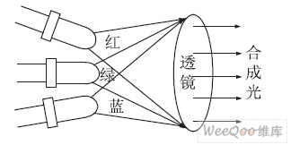
Figure 1 Three-primary color realization of synthetic color light schematic
The brightness of the three primary color LEDs is adjusted by the control circuit, and the color and brightness of the synthesized light passing through the lens are adjusted.
2 dimming device overall plan
As shown in Figure 2, the 87LPC762 MCU transmits data to the three-way D/A converter, converts the digital quantity into analog quantity, and controls the intensity of the red, green and blue LED illumination by the power amplifier circuit, thereby controlling the color of the LED illumination. And brightness, for multiple LEDs using dynamic scanning mode, the two output terminals are controlled by the single-chip microcomputer to output the serial signal with CLK as the reference, and the tri-polar transistors in the switching operation are respectively controlled by the serial-to-parallel conversion device to illuminate the three primary color LEDs respectively. Control of graphic patterns. Finally, the system can perform the functions required for dimming. The serial communication interface is connected to the computer by using the RS232 standard bus, and the pattern or text to be displayed on the computer can be transmitted to the system and displayed.
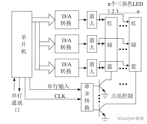
Figure 2 Overall scheme of the dimming device
3 light color adjustment implementation
In Figure 3, the AD558 is a D/A converter chip that converts digital quantities into analog quantities. The MCU connects to DB0-DB7 of AD558 through P0 port to perform parallel data transmission, thereby controlling the output voltage of AD558. The output voltage controls the intensity of LED monochromatic illumination through power amplification. Since the AD558 is an 8-bit D/A conversion chip, when three primary colors are controlled by three D/A respectively, red, green, and blue in the three primary colors can be divided into 28 = 256 outputs, respectively. Any combination can form a maximum resolution of 2563 = 16777216 color and brightness. The software data can be set to any desired resolution value according to actual needs.
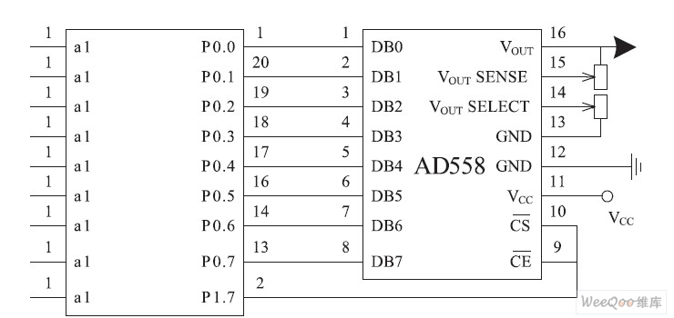
Figure 3 Light color adjustment analog output schematic
4 multi-point LEDs respectively illuminate the scanning implementation
The three pins of the P1 port of the MCU output signals respectively, and the 74LS164 converts the serial signal into a parallel signal. The output terminals Q0-Q7 are respectively connected with the common terminals of the red, green and blue primary LEDs, and can output high in turn under the control of the clock CLK1. Level. This circuit is a serial data control parallel port, so it can be expanded arbitrarily.
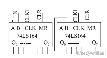
Figure 4 Multi-point LEDs respectively illuminate the scanning implementation schematic
5 Communication between the dimming device and the computer system
As shown in Figure 5, the RS-232 serial communication standard is adopted between the dimming device and the computer system, which specifies the level relationship, load requirements, signal rate, and connection requirements of the transmitter driver and the receiver receiver, MAX232. Mainly used to complete the conversion between TTL level and RS-232 level.
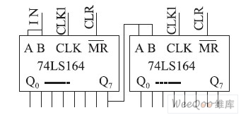
Figure 5 Communication interface diagram between the dimming device and the computer system
6 Conclusion
Designed and produced a set of LED dimming device, which uses the three-channel D \ A conversion output to control the LED red, green and blue primary color output respectively, realizing the wide range and high precision adjustment of semiconductor illumination color and brightness. The serial-to-parallel scan mode enables a system to individually control multiple LEDs, enabling them to form arbitrary static and dynamic patterns or images based on high-precision light control and color control.
The pattern and color and brightness of the matrix of the actual experimental model 128 × 64LED were tested for 8 hours, indicating that the center intensity of the LED is stable at 280 lx ( lx: lux), and the central light intensity decays as the LED temperature increases. At 3%, the expected level of control requirements was reached.
:
Adjustable 12V DC 500W 6/17CH Rack Mounted Integrated Power Supply 1U
This product is based on the standard 19-inch cabinet assembly, meticulous design and manufacture, adopting modular design, input voltage 90V AC--246V AC, can output 5V DC/12V DC/ 24V DC / 48V DC, A total of 16 channels are divided into 4 groups of output, digital display, Each set of voltage can be adjusted, total power 600W, with lightning protection, over-voltage protection , over-current protection , overload protection , over-temperature protection and indicator acousto-optic and alarm function, power outages can be self-locking.
Features:
Use of efficient, environmental protection switching power supply circuit frame
Modular 1U standard 19" rack mount chassis
Small ripple & noise -- video output signal more stable, clearly images
Splitter output -- by-pass failure to protect other equipment to work
Power protection -- Output over-voltage protection, over-current protection, short circuit protection
Application:
It widely used in banks, government units, buildings, office buildings, garden community, square, Factory, prison, road traffic, gas station, ship and other machine rooms, can dock intelligent APPDU system, embedded in the back-end security system management platform, is an ideal intelligent security integrated power supply and Management System.
Product Images:

Power Supply 12Vdc ,Power Supply 12Vdc 5A,Power Supply 12Vdc 10A,Power Supply 12Vdc 2A
Dongguan Xiaoerduo Electronics Co., Ltd. , http://www.steadysmps.com