
As you all know, the development of indoor visible light communication is not ideal. So, what key technologies should be clarified to promote the application of this technology?
In order to meet the requirements of fast, stable, safe and environmentally friendly communication network services, to solve the problems of frequency band tension and bandwidth limitation in radio frequency wireless communication networks, and to deepen the existing radio frequency wireless communication system by deepening the research and discussion of indoor visible light communication system technology. The way in the use of wireless communication networks. In this paper, the channel model analysis of indoor visible light communication system, the modulation and demodulation technology of indoor visible light communication system, and the channel coding technology of indoor visible light communication system are analyzed in detail, aiming to further improve the key technology of indoor visible light communication system in wireless communication network. Use in the middle.
In recent years, indoor visible light communication technology has been more and more widely used in our daily life. Indoor visible light communication technology can meet our indoor indoor network requirements as well as daily indoor lighting . Compared with traditional communication technology, it It has higher privacy and security, can use a wider frequency band, can avoid electromagnetic interference, and can be accessed by wireless communication. Its network coverage is expanded, and the reusability of space is also very good. The advantages make this technology attract the attention of researchers in related fields.
White light LED is the most important kind of visible light source provided by visible light communication system. Its size is smaller than other types, and its voltage, power consumption and life are low. The control of white LED can be realized at normal temperature. Very competitive.
However, the current development of indoor visible light communication technology in China is still not mature, and some application problems cannot be properly solved. This paper will analyze the related problems of indoor visible light communication system, in order to promote the development of this technology in China.
Channel Model Analysis of Indoor Visible Light Communication System
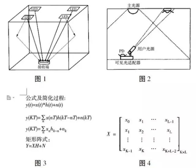
In general, a visible light source LED emits a signal from the transmitting end and relies on the receiving end to receive the signal. When transmitting the signal, the communication system first modulates the intensity of the optical power by the transmitting end, and then uses the LED to transmit, and the signal is transmitted to the receiver through different paths, such as direct reflection and reflection; finally, the receiver transmits the optical path through the optical path. The incoming signal is detected and recovered. The signal transmission scenario is shown in Figure 1.
In the process from the signal being transmitted to being received, it will undergo direct and diffuse reflection (see Figure 2), but the effect of diffuse reflection on the emission and reception of optical signals in the room is small and negligible. Therefore, in order to facilitate the calculation, only the two main optical powers received by the receiving end are used as the main object of the calculation, that is, the first reflected and direct optical signals. The influence of the optical signal from the indoor environment during transmission can be transmitted with a relatively simple linear baseband.
The system indicates that this is the result of the law of its propagation. After the calculation of the diffuse reflection is omitted, the signal of the optical power transmitted to the receiving end for the first reflection and direct transmission can be set to y(t), and the instantaneous power generated when the optical signal is transmitted can be set to x(t), the pulse. The response is h(t), the optical channel noise is n(t), the signal convolution is represented by *, and the value of t is greater than or equal to zero. Because the cause of optical noise is background light, in the calculation, independent Gaussian noise is used as the optical noise in the set value to calculate. The calculation formula and the simplified process of the formula are shown in Figure 3. The final signal transmission cycle is obtained. The matrix is ​​shown in Figure 4. The Y in the formula Y=XH+N represents the sequence of the received signal: Y=[y0,y1,...yk-1]T, H means the channel
The response of the pulse impulse: H = [h0, h1, ... hk-1] T, N is the noise vector: N = [n0, n1, ... nk-1] T. L and K in the cyclic matrix represent the tap length of the channel and the length of the training sequence, respectively.
Indoor visible light communication system modulation and demodulation technology
The modulation of bandwidth affects the speed of LED data transfer and is an important measure of LED modulation capability. The composite lifetime of the PN junction capacitance and the carriers in the active region is the main factor affecting the LED modulation bandwidth. Therefore, we can use multi-chip white light in addition to reducing the parasitic capacitance and reducing the carrier lifetime of the carriers. LED to modulate the bandwidth. In addition, optimizing the external driver circuit is a good way to improve the modulation capability of the LED.
| About Glass Fiber Series Wire |
The insulation material uses 160 pieces /250 pieces non-alkali yarn glass fiber yarn, which is characterized by thin insulation layer, light weight and protective effect on inner insulation.Impregnating varnish used modified epoxy paint, epoxy, conforms to the ROHS certification, with excellent electrical properties and high mechanical and damp and hot resistance, suitable for ac, dc motor, synchronous generator, dry type transformer and high temperature electric appliance coil and winding, the high voltage ac motor, large dc motor, large wind turbines, glass envelope envelope particularly suited to 10 kv transformer and large and medium-sized high-voltage motor winding.
Name
Insulation Glass Fiber Winding Wire
Conductor
Copper
Dimension(mm)
Round: 1.0 ~ 7.0
Rectangular: Thickness(a): 1.0 ~ 10.0
Width(b): 3.0 ~ 35
Insulation Material Type
Fiber Glass
Insulation Thickness
Singer, double or according to your requirement
Standard
IEC; ISO9000; ISO9001; IATF16949
Packing
100kg ~120kg ply-wood spool (250*500)
Application
Oil-immersed transformer windings, medium
and large electrical motor and power substations, etc.
Glass Fiber Aluminium Wire
Name
Insulation Glass Fiber Winding Wire
Conductor
Aluminum
Dimension(mm)
Rectangular: Thickness(a): 1.0 ~10.0
Width(b): 3.0 ~ 35
Insulation Material Type
Fiber Glass
Insulation Thickness
Single, double or according to your requirement
Standard
IEC; ISO9000; ISO9001; IATF16949
Packing
50kg~150kg ply-wood spool (250*500/
250*550/ 250*600)
Application
Oil-immersed transformer windings, medium
and large electrical motor and power substations, etc.
Glass Fiber Series Wire
Copper Flat Wire,Glass Fiber Series Wire,Double Glass-Fiber Copper Flat Wire,Fiberglass Copper Wire For Motor
HENAN HUAYANG ELECTRICAL TECHNOLOGY GROUP CO.,LTD , https://www.huaonwire.com