
Today, car users are becoming more sensitive to fuel consumption, expecting energy-saving fuel bills, and objectively helping to reduce environmental impact. In order to match this trend, automakers have adopted various ways to reduce consumption. One way is to apply automatic “Start/Stop†function in new models to help reduce fuel consumption. Increase sales selling points.
The so-called automatic start-stop function means that when the car stops due to traffic jam or red light, these innovative systems automatically shut down the engine (extinguish); when the driver's foot moves from the brake pedal to the accelerator pedal, the engine is automatically restarted. (ignition). This will help reduce unnecessary fuel consumption and reduce emissions during busy periods of urban driving and stop-and-go traffic.
The effect of automatic start-stop system on the vehicle power system
But such innovative systems also present some unique challenges for automotive electronics design. Because when the engine is restarted, the battery voltage can drop to 6.0 V or even lower. In a typical automotive power architecture, a typical electronic module includes a reverse polarity diode that protects the electronic circuit in the event of a jump start and a jumper cable reversal. The protection circuit itself creates a voltage drop that causes the downstream circuit voltage to be only 5.5 V or less. Since many modules still require a 5 V supply, an excessively low dropout voltage leaves the buck power supply with insufficient headroom to function properly. Therefore, the traditional automotive power architecture is not suitable for automatic start-stop systems.
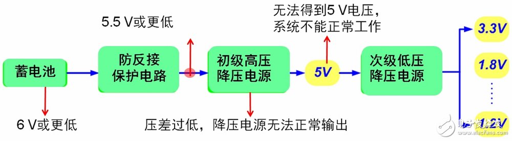
Figure 1: Traditional automotive power architecture and its problems.
Automatic start and stop system common power solution
There are three common scenarios for selecting the appropriate power architecture for an automatic start-stop system. One solution is to use a low dropout (LDO) linear regulator or a low dropout switching power supply such as the NCV8852 from ON Semiconductor. This is an automotive-grade, non-synchronous buck controller that accepts a wide input voltage range of 3.1 to 36 Vdc and withstands a 44 V load dump. The advantage of this scheme is that the system voltage can work normally when the input voltage is as low as 5.5 V. However, the disadvantage is that if the input voltage drops to a lower level, the system will not work properly.
Another solution is to use a buck-boost power supply as the primary power source, such as the single-ended primary inductor converter (SEPIC) circuit built with ON Semiconductor's NCV8871 or NCV898031. The outstanding advantage of this solution is that the system can work normally even if the input voltage is as low as 4 V. But its shortcoming is to change the design, the system is relatively complicated.
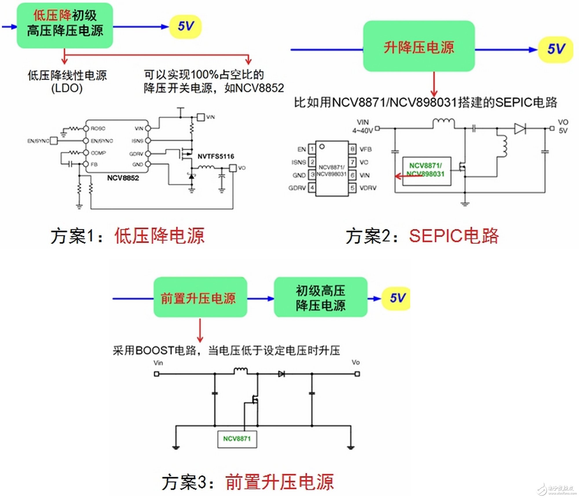
Figure 2: Common power scheme for an automatic start-stop system.
The third option is to use a pre-boost power supply before the primary high-voltage step-down power supply. For example, the NCV8871 from ON Semiconductor can be used to construct a pre-boost circuit that boosts when the input voltage is lower than the set voltage. The advantage of this solution is that the system can work normally when the input voltage is lower than 4 V, and there is no need to change the power supply design. However, the disadvantage is that when the battery voltage is normal, additional power consumption is generated, which is not conducive to reducing energy consumption as much as possible.
ON Semiconductor's improved pre-boost power solution for start-stop systems - NCV8876
As mentioned above, these three common automatic start-stop system power solutions have their own advantages and disadvantages. In response to this situation, ON Semiconductor introduced the NCV8876, a non-synchronous boost controller for automotive auto start-stop systems, which is mainly used to provide sufficient operating voltage for subsequent circuits when the vehicle is automatically started and stopped. It is an improved pre-boost power solution designed to take full advantage of the pre-boost power solution while trying to avoid its shortcomings.
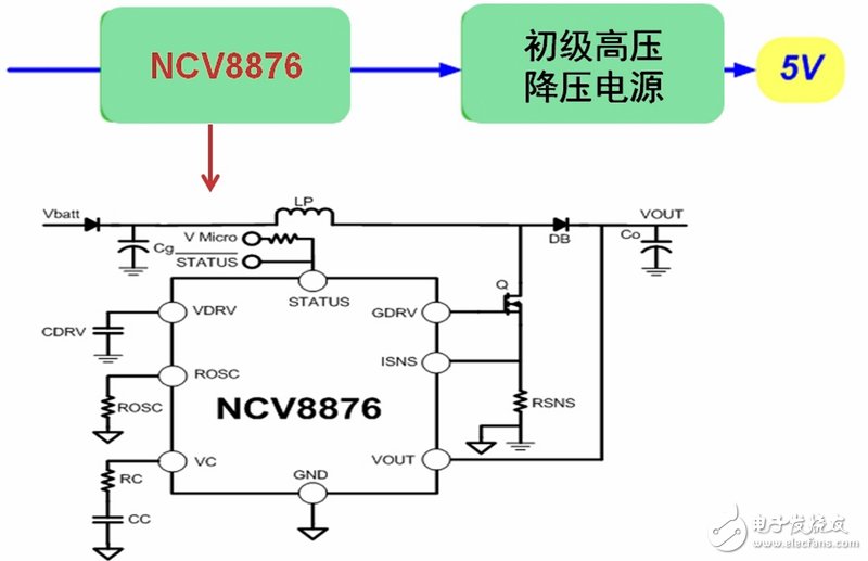
Figure 3: Typical application circuit for ON Semiconductor's improved pre-boost power solution, the NCV8876.
This article is selected from the Electronic Consumers Network July "Auto Electronics Special Issue" Change The World column, please indicate the source! 
Double Sided PCB - the most popular type of PCB in the industry
While single-sided PCBs are simple and ideal to use when possible, many circuits require two sides. Double-sided PCB boards offer a wide variety of possibilities for circuit board designers because they have more surface area and flexibility when routing traces. Using two sides instead of one also allows for a smaller board size overall, which can be important when building small-scale, integrated devices.Double-sided PCB is one of the most common types of PCB. Moreover, the two-sided PCB and the single-sided PCB are basically the same to some extent. The difference is that the single-sided PCB has only one conductive surface. That is to say, the one-sided PCB has copper on one side of the board, but the two-sided PCB has conductive layer on each side. The dielectric layer is surrounded by the copper layer of the circuit and welding masks on both sides. Technically, single-sided circuit boards will not be copper plated in boreholes. Passing holes allow manufacturers to create traces on both sides that are adjacent to each other and connected between layers. PCB manufacturers use double-sided PCBs for products that require elementary to intermediate circuit complexity. This type of PCB does not provide as much circuit complexity or density as multi-layer PCB, but it is the most economical choice in many applications.
Nowadays, double-sided Printed Circuit Boards can be designed and manufactured in a variety of ways, including silver and gold surface treatment, high and low temperature and solder coating. This versatility enables them to power almost unlimited numbers of projects at cost-effective prices. Because of these advantages of double-sided PCB, double-sided PCB technology has become the most popular type of PCB in the industry.

What is Double-Sided PCB?
Strictly speaking, the Double-Sided PCB is one kind of the important PCB boards which is useful in PCB industry. They allow for the routing of traces around each other by jumping between a top and bottom layer by way of vias. Generally speaking, There are lines on both sides! The common PCBs can be seen such as, Rigid PCB , Flexible circuit board, Aluminum PCB and Metal Core PCB.
It need circuits on both sides. Via is the holes on boards, coated with metal and it can connect wires on both sides. Because the area of Double-sided PCB is twice as large as the Single-sided PCB, and because the wiring is interleaved, which is better suited for circuits that are more complex.
Someone may feel confused that if one Double-sided PCB, wires on both sides while Electronic parts only one side, is this a Double-sided board or a single onel? The answer is obvious. This kind of board is a Double-sided board, it's just install a component on the Double-sided board.So the question is, if a double-sided PCB has circuits on both sides, but only one side has electronic accessories, is it a double-sided PCB or a single-sided PCB? The answer is obvious. This kind of board is a double-sided circuit board. It only installs a component on the double-sided PCB.
Double sided circuit boards are one of the most popular types of PCBs as they enable manufacturers to produce more complex circuits, which can benefit uses in higher technology applications and electronics. There is an abundance of applications and electronics which double sided PCBs can be used in including: lighting systems, vending machines, amplifiers, car dashboards, and many more.
Double Layers PCB expands design capability and reduces physical sizes.

Double-Sided PCB material
The manufacturing base material of PCB is rigid glass fiber laminate. In the actual manufacturing process, many types of PCB materials can be used. Which material to use is determined by the PCB designer to meet electrical, temperature and other related characteristics. However, the standard material commonly used is fiberglass, which we usually call FR4.
FR, which technically stands for "flame retardant", does not mean specific material, but refers to material grade. However, it is a glass fiber reinforced epoxy laminate with flame retardant standard UL94V-0.
FR4 is the most common and typical choice of rigid PCB materials. Usually we classify them into three categories:
Normal Tg = Material melting point over 130 degrees Celsius
Medium Tg = Material melting point more than 150 degrees Celsius
High Tg = Material melting point more than 170 degrees Celsius
Double-Sided PCB construction

Double Sided PCB Layers


Benefits of Double-Sided PCBs
Double-sided PCB is a widely used component in various applications, because it can achieve greater flexibility in designing more complex circuits. The following are some advantages of double sided PCB:
- Improving circuit density and complexity: By having conductive layers on both sides, the component space of double-sided PCB is twice as large as that of single-sided PCB. It can easily increase the density and complexity of the circuit.
- Double-sided PCB is widely used: Double-sided PCB has circuit complexity and can be used for many common electronic products at reasonable prices. Use double-sided PCB to make popular electronic products for daily use.
- More suitable for more complex projects: Double-sided PCB is the same size as single-sided PCB, but has twice the component space. Design more complex projects with the same amount of space.
- Cost-effective manufacturing: Double-sided PCB has the ability to be used in a large number of projects, and the price is lower than multi-layer PCB, avoiding paying extra costs.
- Provide more design possibilities: at relatively low cost, you can greatly expand the number of projects available for your functions and budget. Creating innovations that a single-tier PCB cannot achieve.
- Redirect the PCB current while keeping the top free: You can use the bottom of the double-sided PCB as grounding copper casting for sinking and output current.
Double sided PCB boards is different from Single-sided PCB.
Single-sided PCB is the basic one, the spare parts are concentrated in one side, and the circuit is concentrated on the other. Because the wires only appear on the one side of themso we called Single-sided PCB. Because the single-sided PCB has many strict restrictions on the design circuit (because only one side, the wiring cannot cross and must move around the individual path), so it only used on earlier circuits.
Single-sided PCB diagram mainly used Network Printing(Screen Printing), that is, resist on copper surface, After etching, mark the welding resistance, and then finish the hole and the shape of the part by punching.
Single-sided printed circuit boards are widely used in many electronics whereas double sided circuit boards are often used in higher technology electronics.
Single-sided printed circuit boards are commonly used in an array of electronics and applications, including: camera systems, printers, radio equipment, calculators, and much more.
Benefits of Single-Sided PCBs
Single-sided circuit boards are considered to be one of the best choices for a wide range of applications due to the advantages that it provides. Here are a few advantages of single-sided printed circuit boards:
- The cost of manufacturing and producing single sided circuit boards are very cost-effective and affordable due to the simple and basic designs. These types of PCBs are widely understood by various manufacturers which makes single-sided boards the best choice for circuit designs that are simple and low density.
- As single-sided boards are less complex, there will undoubtedly be fewer problems during the manufacturing stage, which enables manufacturers to produce these boards at higher volumes and at faster speeds. Due to this, they are commonly used in many applications and electronics.
With higher volume orders, single-sided circuit boards can be more affordable and available at reduced costs.
Double-Sided PCB Applications
Many of the electronics found in everyday life function on double-sided PCBs. Applications of double-sided PCBs include:
- Industrial controls
- Power supplies
- Converters
- Control relays
- Instrumentation
- Regulators
- UPS systems
- Power conversion
- HVAC
- LED lighting
- Hard drives
- Printers
- Phone systems
- Power monitoring
- Automotive dashboards
- Line reactors
- Test equipment
- Amplifiers
- Traffic systems
- Vending machines
Double-Sided PCB fabrication
Double Sided PCB Home Made DIY
DIY Double Sided PCB
Learn more about our products and services through the following links:
- Reflow double sided PCB
- A Collection of Questions on Double Sided PCB
- Advantages of Double Sided PCB
- Double Sided Metal Core PCB
- Double sided Rigid PCB
Double Sided PCB
2 Layer PCB,Double Sided Fr4 PCB,pcb prototype service,Double Layer PCB
JingHongYi PCB (HK) Co., Limited , https://www.pcbjhy.com