
In recent years, various mobile robots have emerged. Whether it is wheeled or tracked, how to make mobile robots move is the core task. To enable the robot to implement a series of functions such as environmental awareness, robot control, and navigation planning, it needs the support of the operating system, and ROS is one of the most important software platforms. It has been widely used in scientific research.
However, there are not many books on ROS and there are even fewer learning communities available in the country. In this issue, you will learn how to use ROS to design mobile robots.

Sharing guests Li Jinbang: Founder and CEO of EAI Technology, graduated from Beijing Institute of Technology with a master's degree. She has worked in NetEase, Snowball, and Tencent's technology department for years of research and development experience in linux. Co-founded EAI Technology in 2015, responsible for the development of SLAM algorithm and related positioning and navigation software product development. EAI Technologies focuses on mobile robotics, providing consumer-grade high-performance laser radar, slam algorithms, and robot mobile platforms.
The three parts of the mobile robotThe so-called smart movement means that robots can autonomously plan routes and avoid obstacles according to changes in the surrounding environment and reach the target area.
The robot is a simulation of various human behaviors. Imagine what organ coordination is required for people to walk? First look at the surroundings with your eyes, and then use the brain to analyze how to get to where you want to go. Then use your legs to walk over and continue until you reach the target address. If the robot wants to realize intelligent movement, it also needs the close cooperation of the three parts of the eye, brain and leg.
legThe "leg" is the basis for robot movement. The “legs†of robots are not limited to human-like or animal-like legs. They can also be wheels, caterpillars, etc. Components that allow the robot to move around can all be referred to as “legs.â€
The legged advantages of humanoids are: they can move under complex road conditions (such as climbing stairs) and can more vividly imitate human actions (such as dancing). The disadvantages are: the structure and control unit are more complicated, the cost is high, and the movement is slow. Wait.
So most of the mobile robots are wheeled robots. The advantages are that the wheels are simple in design, low in cost, and fast in moving. Wheeled vehicles are also divided into two types: two-wheeled balancing vehicles, three-wheeled vehicles, four-wheeled vehicles, and multiple-wheel vehicles. At present, the most economical and practical are two driving wheels + one universal wheel.
eye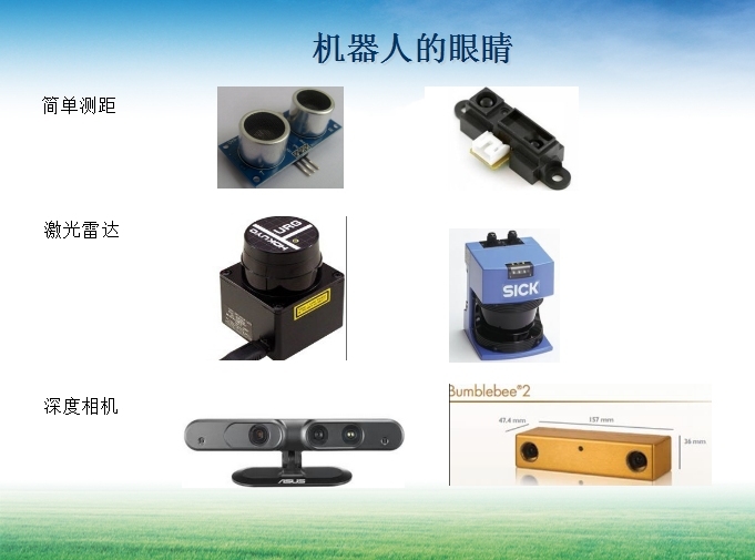
The robot's eye is actually a sensor. Its role is to observe the surrounding environment, suitable for robot eyes with lidar, vision (depth camera, single and dual cameras), auxiliary (ultrasonic ranging, infrared ranging) and so on.
"brain"The brain of the robot is responsible for receiving the data transmitted by the "eyes", calculating the route in real time and directing the legs to move.
In fact, it is necessary to convert what you see into a data language. How to describe the data, how to achieve a series of problems such as processing logic. The ROS system provides us with a good development framework.
ROS is an operating system built on linux. Its predecessor, the Stanford Artificial Intelligence Laboratory, was established to support Stanford's intelligent robots. It can provide some standard operating system services such as hardware abstraction, low-level device control, common function implementation, inter-process messages, and data packet management.
ROS is based on a graph-like architecture so that processes at different nodes can accept, publish, and aggregate information (eg, sensing, control, status, planning, etc.). At present, ROS mainly supports the Ubuntu operating system.
Some people ask if ROS can be installed in a virtual machine. Generally speaking, it is OK. However, we recommend installing a dual system and using Ubuntu to run ROS.

In fact, ROS can be divided into two layers, the lower layer is the operating system layer described above, and the upper layer is a variety of software packages contributed by various user groups to achieve different functions, such as positioning mapping, action planning, perception, simulation, and so on. ROS (lower level) uses BSD licenses, all of which are open source software, and can be used for research and commercial purposes free of charge, while high-level user-supplied packages use many different licenses.
Using ROS to Move RobotsFor two-dimensional space, the use of linear velocity + angular velocity can achieve random movement of wheeled machines.
Line speed: describes the speed of the robot moving forward and backward
Angular speed: describes the angular speed of the robot's rotation
Therefore, controlling the movement of the robot is mainly to convert the angular velocity of the line speed into the velocity of the right and left wheels. Then, by means of the wheel diameter and the wheel spacing, the linear velocity and the angular velocity can be converted into the speeds of the left and right wheels.
One of the key issues here is the choice of encoders and the speed control of the pid.
The choice of encoder: The general encoder and the wheel are on one axis. At present, if the speed is less than 0.7m/s, the encoder is selected between 600 and 1200 keys. However, it should be noted that the encoder is best to use two-wire, A, B two-wire output, A- and B-to-B output to the difference of 90 degrees, this can prevent jitter. Anti-shake is more accurate after the mileage calculation.
The control of the speed of the left and right wheels is feedbacked by the wheel encoder and realized by adjusting the PMW of the motor in real time. The odometer of the car is calculated in real time, and the position of the car is changed.
The position change of the calculation vehicle is calculated by the encoder. If the wheel slips, the calculated change and the actual change may be different. To solve this problem, it is actually to see that the problem is even more serious. It takes only 4.9 meters to walk 5 meters, or it takes 180 degrees and only 179 degrees is important.
In fact, the inaccuracy of the angle has a greater impact on the car. In general, the linear distance accuracy of the trolley can be controlled within centimeters, and the accuracy can be controlled at 1%~2% in terms of angle. Because angles are more important parameters, many people use gyros to correct them.
So sometimes we ask how high the accuracy of the car? The realization of such a problem has been relatively high precision, it is difficult to avoid slipping and other issues, it is impossible to achieve 100% accuracy.
It is already acceptable for the car to be self-built for map navigation in terms of distance and angle. To improve the accuracy, it may be necessary to assist with other devices, such as laser radar, which can perform secondary detection and correction. .
The storage format of lidar data, it will first have a size range, if the out of range is invalid. There are several sampling points, so that the lidar can tell you how many degrees there is a sampling point.
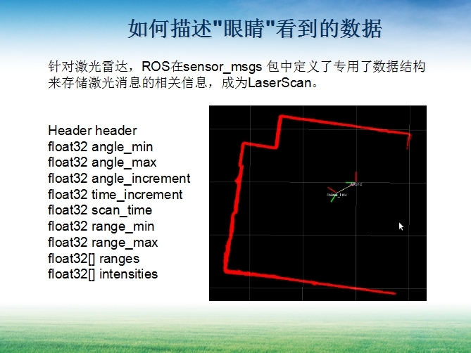
In addition, the last Intensities is to tell everyone the accuracy of the data, because the laser radar is also the highest point of the data, there is a certain degree of accuracy. The above ppt actually uses a laser radar to sweep the shape of a wall.
There is no point in sweeping out a static shape with a laser radar. The significance of radar construction is actually to create a map of the room.
How to draw a map?The first step is to collect eye data:
For LiDAR, ROS defines a dedicated data structure in the sensor_msgs package to store laser-related information, becoming LaserScan.
It specifies the effective range of the laser, the sampling angle of the scanning spot, and the measurement value of each angle. Laser radar 360-degree real-time scanning, real-time detection of obstacles in the distance, shape and real-time changes.
The second step is to turn the data the eye sees into a map:
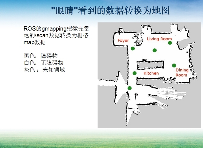
ROS's gmapping converts the lidar's /scan data to raster map data, where black represents obstacles and white represents white space. Smooth, gray: unknown. With the movement of the robot, the lidar can observe whether there are obstacles in the same position in a plurality of different positions. If the threshold of the obstacle exceeds the set value, it is determined that there is an obstacle; otherwise , there is no obstacle in the calibration. The dimensions of obstacles, blank areas, and unknown areas are represented in different shades of gray—a raster map. Easy to locate and navigate in the next step.
Sometimes there will be a straight wall, but the robot can't walk straight. The problem may be that the robot's wheels appear to be slippery and other problems. However, the maps drawn at this time may also be embarrassing. This situation can be avoided by adding a gyro. Due to the characteristics of Lidar, sometimes encountering black or mirrors can cause inaccurate ranging.
The current solution is not to use laser radar or laser radar and ultrasonic assistance.
ROS maps are multi-layered. I can put multiple laser radars at different heights to superimpose them together to draw a map together. After the map is drawn, you can perform positioning and navigation.
How to locate and navigate?Positioning: Actually it is a probabilistic positioning, not a 100% accuracy. According to the shape of the obstacles scanned by the laser radar, the shape of the map is matched to determine the probability of the robot's position.
The success of the positioning of the robot has a lot to do with the characteristics of the map. If the characteristics of the area are obvious, then the robot can easily determine its position. If it is difficult to locate the problem, you may need to specify the initial location, or add a led to identify the location, or other positioning equipment to help locate.
The current vision through color or light technology is more and more.
Navigation: Global Path Planning + Local Adjustment (Dynamic Obstacle Avoidance)
Navigation is actually a global positioning. First, planning is based on the existing maps, but local route planning will be carried out during the operation. But the overall situation is still based on the overall path.
The workload in navigation is still very large. For example, the path planning of the sweeping machine is not the same as the path planning of the service robot. The sweeping robot may have a full-coverage map with a corner. The service robot mainly focuses on the specified path or the shortest path. Planning, this part is the largest piece of ROS workload.
Path planning varies greatly according to different application scenarios, but ROS provides basic path planning development packages. On this basis, we will do our own path planning.
Robot description and coordinate system transformation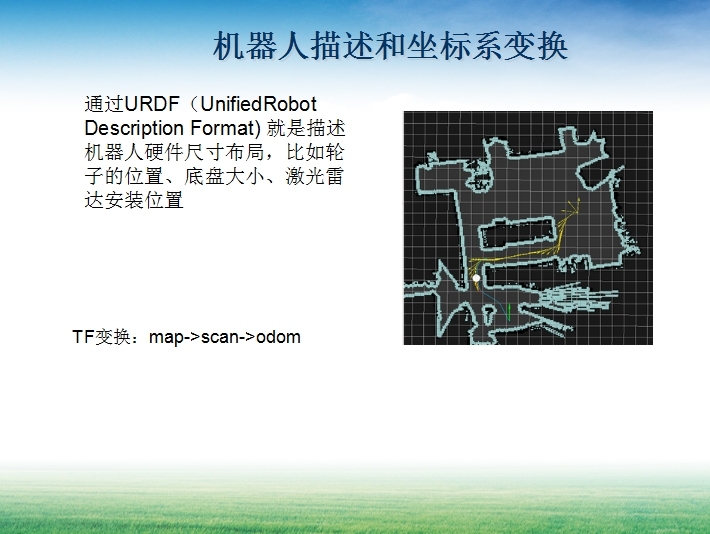
During navigation, which areas can pass, depending on the robot shape and other information, ROS through URDF (UnifiedRobot Description Format) is to describe the hardware layout of the robot, such as the position of the wheel, chassis size, lidar installation position, which will affect the coordinate system Conversion.
The premise of the coordinate system is that each frame can only have one parent frame, and then go up some eyes or associations.
The installation position of the lidar directly affects the /scan output data. Therefore, the relative position of the laser radar and the robot must be coordinate transformation in order to convert the data of the laser radar into the data of the robot's perspective.
ROS's coordinate system ultimately boils down to three standard frameworks that can simplify many common robotic problems:
1) Globally accurate, but partially discontinuous frames ('map')
2) Globally inaccurate, but partially smooth frames ('odom')
3) Robot's own frame ('base_link')
A variety of sensors (such as lidar, depth camera, and gyroscope accelerometer, etc.) can compute the base_link and odom coordinate relationships, but because there can be only one parent frame per frame, there can be only one node (eg robot_pose_ekf Fused multiple sensors) publish the base_link and odom coordinate relationships.
The base link's own coordinate system, because different components are mounted on different positions on the robot, must correspond to the base link coordinate system, because all sensors are to "see" through the robot's perspective.
Some friends asked me that when the Lidar was building a map, the map would become chaotic after the car moved. This is because the car's chassis coordinate system and Lidar's coordinate system are not calibrated accurately.
Association between map and odomBecause the trolley moves need a local connection, for example, the cart is moving forward and accumulates continuously. This is the role of the odometer. The map plays a global and discontinuous role and passes the lidar and map.
If you want to learn ROS, the change of coordinate system is an important point. Another point in the transformation of the coordinate system is that each frame has only one parent frame. Sometimes two coordinates are associated with it, that is, A and B are associated. B is associated with C, not B and C. A association.
The parent-child relationship of the three coordinate frames is as follows:
Map -> odom -> base_link
In fact, both map and odom should be associated with base_link, but in order to comply with the principle of “only one parent frame per frameâ€, according to the relationship between map and base_link and odom->base_link, the coordinate relationship between map and odom is calculated and published. .
The odom->base_link coordinate is calculated and published by the odometer node.
The coordinate relationship of map -> base_link is calculated by the positioning node, but it is not released. Instead, the coordinate relationship of map->odom is calculated using the coordinate relationship of receiving odom->base_link and then published.
When there is only an odometer, there is no Lidar, but you can also run, but you must first simply avoid obstacles based on the preset map.
Wonderful question and answerQ: Is there any improvement in real-time performance of ROS?
A: Real-time improvement depends on the design of ROS 2.0. In fact, the progress of ROS 2.0 has been published online. But in fact his progress is still a certain distance from the actual application, at least not stable in the second half of this year, but you can go to study his code, he has great improvements in memory management, thread management, real-time .
Q: vSLAM has high memory and CPU requirements. In practical projects, what hardware configuration does Teacher Li use? How big can you do?
A: This is indeed the case. At present, we still use laser radar and sensor assistance. This has little to do with the size of the map. It is mainly related to the complexity of the terrain obstacles.