Alternator structure
This article refers to the address: http://
First and sixth tube alternator structure
The alternator is generally composed of a rotor, a stator, a rectifier, and an end cover.
Figure 2-5a shows the JF132 type alternator assembly 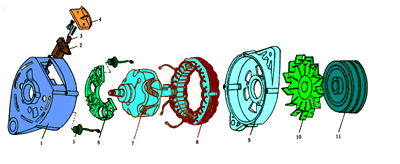
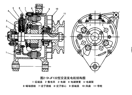
JF132 type alternator structure diagram shown in Figure 2-5b
JF132 type alternator structure diagram shown in Figure 2-5c 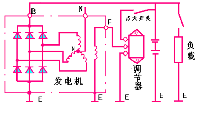
(a) rotor
The function of the rotor is to generate a rotating magnetic field.
The rotor consists of a claw pole, a yoke, a field winding, a collector ring, and a rotor shaft, as shown in Figure 2-6.
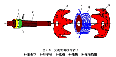
Two claw poles are press-fitted on the rotor shaft, and each of the two claw poles has six bird-shaped magnetic poles, and the claw pole cavity is provided with a field winding (rotor coil) and a yoke.
The collector ring is composed of two copper rings insulated from each other. The collector ring is press-fitted on the rotor shaft and insulated from the shaft, and the two collector rings are respectively connected to both ends of the field winding.
When the two collector rings are connected to direct current (through the brush), a current flows through the field winding and generates an axial magnetic flux, so that the claw pole is magnetized to the N pole and the other magnet is magnetized to the S pole, thereby forming Six pairs of magnetic poles that are interlaced. When the rotor rotates, a rotating magnetic field is formed.
The magnetic circuit of the alternator is: yoke → N pole → air gap between the rotor and the stator → stator → air gap between the stator and the rotor → S pole → yoke. See Figure 2-7.
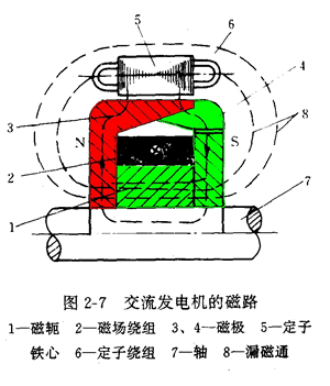
(two) stator
The function of the stator is to generate alternating current.
The stator is formed by a stator core and a stator winding. See Figure 2-8A

The stator core is formed by stacking silicon steel sheets with grooves in the inner ring, and the wires of the stator windings are embedded in the slots of the core.
The stator winding has three phases, and the three-phase winding adopts a star connection or a triangular (high power) connection to generate three-phase alternating current.
The three-phase winding must be wound according to certain requirements in order to obtain three-phase electromotive force with the same frequency, equal amplitude and phase difference of 120°.
1. The distance between the two active edges of each coil should be equal to the spatial distance occupied by one pole.
2. The distance between the beginning of the adjacent coil of each phase winding should be equal to or multiplied by the distance occupied by the pair of poles.
3. The starting edge of the three-phase winding should be separated by 2Ï€ + 120o electrical angle (the space occupied by a pair of magnetic poles is 360o electrical angle)
Example: Three-phase winding winding of domestic JF13 series alternator is shown in Figure 2-8B
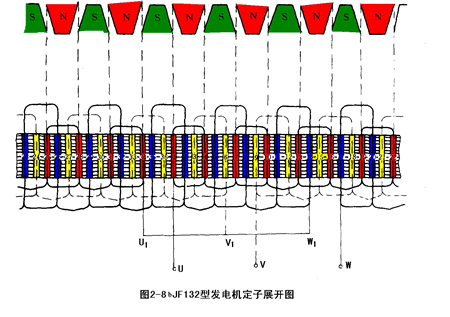
The structural parameters are as follows: Pole pair p 6 pairs of stator slots z 36 slots stator winding phase number m 3 phase each coil turns N 13 åŒ winding coupling method Y-type coupling in domestic JF13 series alternator, a pair of magnetic poles The spatial position of 6 slots (60o electrical angle per slot), one magnetic pole occupies the spatial position of 3 slots, so the position of the two effective sides of each coil is 3 slots, and the phase of each phase winding is adjacent to the beginning of the coil The distance between the three slots of the three-phase winding can be two slots, eight slots, 14 slots, and the like.
(three) rectifier
The function of the alternator rectifier is to convert the three-phase alternating current of the stator winding into direct current.
The rectifier of the 6-tube alternator consists of six silicon rectifier diodes composed of three-phase full-wave bridge rectifier circuits, and six rectifier tubes are press-fitted (or soldered) on two boards.
1. Automotive silicon rectifier diode features (1) large operating current, forward average current 50A, surge current 600A;
(2) The reverse voltage is high, the reverse repeating peak voltage is 270V, and the reverse repeating peak voltage is 300V;
(3) Only one lead is shown in Figure 2-9. And some diode leads are positive, some diode leads are negative, the tube with the positive lead is called the positive tube, and the tube with the negative lead is called the negative tube, so the rectifier diode has the positive diode and the negative diode.
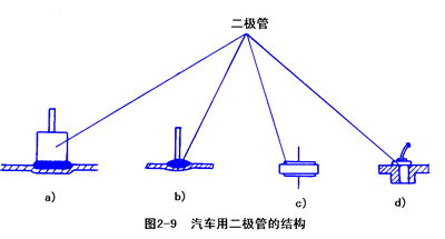
2. The installation of the rectifier tube installs the positive tube on an aluminum heat sink, called the positive rectifier plate; the negative tube is mounted on another aluminum heat sink plate, called the negative rectifier plate, and the generator back cover can also be used instead of the negative rectifier plate. . See Figure 2-10.

There is an output terminal B (output of the generator) on the positive rectifier.
Ground directly on the negative rectifier board. The negative rectifier plate must be connected to the housing.
The shape of the rectifying plate varies from horseshoe to rectangle to semicircle. See Figure 2-11.
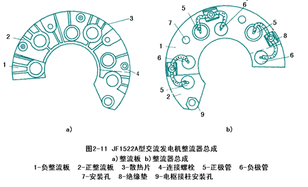
(four) end cover
The end cap is generally divided into two parts (front end cover and rear end cover) to function as a fixed rotor, stator, rectifier and brush assembly. The end cap is generally casted with aluminum alloy, one can effectively prevent magnetic leakage, and the other is that the aluminum alloy has good heat dissipation performance.
The back cover is equipped with a brush assembly, which is composed of a brush, a brush holder and a brush spring. The function of the brush is to introduce the power source through the collector ring into the field winding. See Figure 2-12

The connection of the magnetic field winding (two brushes) and the generator is different, so that the generator is divided into two types: the inner ground type and the outer ground type. Internal iron generator: The generator of the magnetic field winding negative brush is directly connected to the iron (directly connected to the housing). See Figure 2-13a 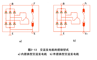
2. External iron generator: The two brushes of the field winding are both insulated from the housing. See Figure 2-13b
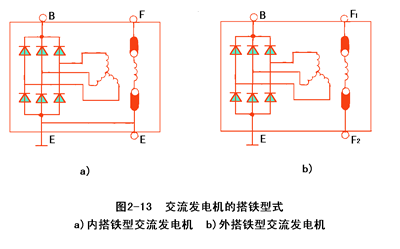
The magnetic field winding negative pole (negative brush) of the external iron generator is connected to the regulator, and then the iron is passed after passing.
Two, eight tube alternator
The basic mechanism of the 8-tube alternator (for Xiali vehicles) and the 6-tube alternator is the same. The difference is that the rectifier has 8 silicon rectifier diodes, 6 of which form a three-phase full-wave bridge rectifier circuit. There are 2 neutral diodes, one positive tube is connected between the neutral point and the positive pole, and one negative electrode is connected between the neutral point and the negative pole. Full-wave rectification of the neutral point voltage. (See Figure 2-14)
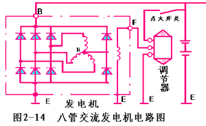
Tests show that an alternator with a neutral point diode can increase the power of the generator by 10% to 15% under the same structure.
The principle of neutral point diodes to increase generator power:
The neutral point voltage of the alternator is the third harmonic, and as the generator speed increases, the third harmonic voltage of the neutral point also rises. See Figure 2-15
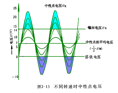
When the instantaneous value of the neutral point voltage is higher than the highest value of the three-phase winding, the neutral point positive tube conducts the external output current; the current loop is: neutral point → neutral point positive tube → load → a certain negative tube → stator winding → Neutral point. See animation 2.
When the instantaneous value of the neutral point voltage is lower than the lowest value of the three-phase winding, the neutral point negative tube conducts the external output current; the current loop: neutral point → stator winding → a certain positive tube → load → neutral point negative tube → Neutral point. See animation 2
Since the neutral point participates in the external output, the output power can be increased.
Third, 9-tube alternator (more applications in Japan)
The basic structure of the 9-tube alternator is the same as that of the 6-tube alternator, the difference being the rectifier. The rectifier of the 9-tube alternator is an alternator consisting of 6 high-power rectifier diodes and 3 low-power excitation diodes.
Among them, 6 high-power rectifier diodes form a three-phase full-wave bridge rectifier circuit. The external load power supply 3 small power tube diodes and three high-power negative pole tubes also form a three-phase full-wave bridge rectifier circuit to supply power to the generator magnetic field. Therefore, three small power tubes are called excitation diodes.
9 tube alternator circuit shown in Figure 2-16

The role of the charging indicator is specifically described in the next section.
Four, 11-tube alternator (such as Santana car generator) as shown in Figure 2-17
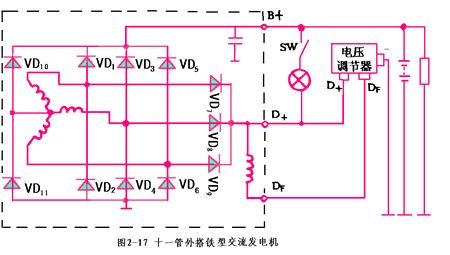
The rectifier of the 11-tube alternator consists of 8 high-power rectifier diodes (two of which are neutral diodes) and three magnetic field diodes. The other structure is the same as the 6-tube alternator.
Five, brushless alternator
Since there is no brush and collector ring, there is no fault such as excitation instability or generator power generation due to wear and contact failure of the brush and the collector ring; at the same time, there is no spark during operation, and radio interference is also reduced.
The brushless alternator is divided into three types: claw pole type, excitation type and permanent magnet type.
(1) Claw pole brushless alternator is shown in Figure 2-18
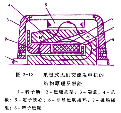
1. Structure and working principle of claw pole brushless alternator The clawless brushless alternator field winding is stationary. It is fixed to the rear end cover by a yoke bracket, so no brush is needed.
Only one of the two claw poles is directly fixed to the rotor shaft of the motor, and the other claw pole is fixed to the front claw pole by a non-magnetic coupling ring. When the rotor rotates, one claw pole drives the other claw pole to rotate together in the stator. When the direct current is passed through the field winding, the claw pole is magnetized, and a rotating magnetic field is formed. The magnetic circuit is shown in Figure 2-18.
2. Advantages (1) Simple structure, convenient maintenance and reliable operation (2) There is no power generation instability or power failure caused by poor contact between the brush and the collector ring.
3. Disadvantages (1) Difficult connection process between claw poles (2) Due to the increased clearance in the magnetic circuit, the excitation current needs to be increased at the same output power of the generator.
(2) Exciter type brushless alternator is shown in Figure 2-19 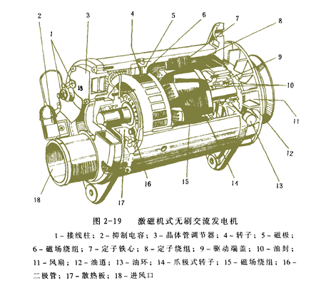
Figure 2-19 shows a brushless alternator with an exciter produced by Bosch, Germany. It is actually based on a claw-pole three-phase alternator, adding a small silicon rectifier alternator specially designed for its excitation, called the exciter (4, 5, 6 in the figure), the exciter The field windings are fixed while the three phase windings are rotating. When the generator rotates, three-phase alternating current is induced in the three-phase winding of the exciter rotor 4, and after being diode-rectified inside the generator, it becomes direct current, and is directly supplied to the magnetic field winding 15 of the claw-pole three-phase alternator to generate power. .
The advantage of this brushless generator is that there is no additional air gap in the magnetic circuit, so the magnetic leakage is small, the output power is large, but the structure is complicated.
(3) Permanent magnet brushless alternator
This type of generator differs from a conventional generator in that it uses a permanent magnet as the rotor pole to generate a rotating magnetic field, which not only removes the brush and slip ring, but also eliminates the need for field windings and claw poles. The structure is simple and reliable, and the service life is long.
Commonly used permanent magnet materials for the rotor are ferrite, chromium nickel cobalt, rare earth cobalt, neodymium iron boron and the like.
Since the rotor is a permanent magnet structure, the intensity of the generated rotating magnetic field is constant and non-adjustable. Therefore, the output voltage of the generator cannot be adjusted by a conventional alternator by controlling the field current through the regulator. In order to solve the voltage regulation problem, a voltage regulator can be used in combination with a three-phase half-controlled bridge type rectification method, so that the output voltage of the generator does not change greatly with the rotation speed.
Figure 2-20 is a schematic diagram of the voltage control of a permanent magnet generator. Three common anode silicon diodes VD1, VD2, VD3 and three common cathode thyristors VT1, VT2, and VT3 form a three-phase half-controlled bridge rectifier circuit. In addition, a three-phase full-wave rectification circuit is composed of silicon rectifier diodes VD1 to VD6, which provides a trigger voltage for the thyristor control electrode, and is connected to one contact of the voltage regulator, and the other contact is connected to the gate of the thyristor, the voltage regulator The coil is connected in parallel to the output of the three-phase half-control bridge. The voltage control principle is as follows:
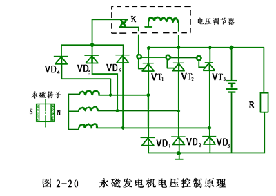
At low speed, the contact K is closed, and the thyristor control electrode is turned on by the forward trigger voltage. When the rotational speed reaches a certain value, the rectifier bridge can provide a full-wave rectified voltage to the battery and the load. When the rectified output voltage rises above the rated voltage as the rotational speed increases, the contact K is opened (due to the increase in coil suction), the thyristor is turned off due to the loss of the forward trigger voltage, and thus the rectified output voltage is lowered. When the rectified voltage drops to a certain value, the current in the voltage regulator coil decreases, the suction force decreases, and K is closed, and the three thyristors are again triggered to conduct, and the rectified output voltage is raised again. Repeatedly, the output voltage can be controlled within a specified range. (Contact adjusters are currently replaced by electronic or computer controlled regulators)
The advantages of permanent magnet alternator are as follows:
1. The utility model has the advantages of small volume, light weight, simple structure, convenient maintenance and long service life. For example, a 750W ferrotitanium-boron permanent magnet generator is equivalent in weight to a 350W ordinary alternator. The rotor has no wear parts other than the bearing and has ventilation holes to cool and dissipate heat, so the life can be more than doubled.
2. Since the transmission ratio is large, that is, the engine speed is low and the generator speed is high, the generator charging performance is good at low engine speed.
3. Larger than the power, can save metal materials.
4. Without excitation loss, the efficiency can be increased by more than 10%.
5. In the voltage controller, since only a current of about 10 mA is passed through the contacts, the contact wear can be reduced, and the voltage regulation structure is simple.
6. Since the magnetic permeability of the permanent magnet is close to the magnetic permeability of the air, the magnetoresistance of the armature reaction is increased, so that the non-sinusoidal distortion of the induced potential is reduced, and the output power is increased.
Sixth, with pump alternator
The generator with the pump alternator is exactly the same as the ordinary alternator. The difference is that the rotor shaft is very long and protrudes from the rear end cover. The outer spline is connected with the internal spline of the vacuum pump to drive the vacuum pump and the generator. The rotor rotates synchronously to evacuate the vacuum cylinder in the brake system of the vehicle, and provides a vacuum source for the vacuum booster of the brake system. It is mainly used for diesel engines without a vacuum source (the gasoline engine can directly obtain vacuum from the intake manifold). During braking, the throttle is almost closed and a high vacuum is created in the intake manifold, while the diesel engine has no throttle. Figure 2-21 shows the appearance of the domestic JFB2525 pump AC generator. 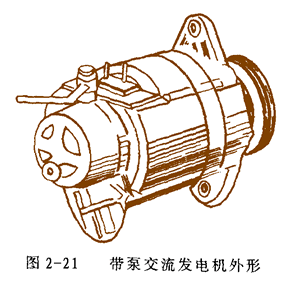
Seven, car double rectifier generator
The double-rectifier generator is a new type of alternator, which greatly improves the low-speed charging performance and high-speed maximum power output of the conventional alternator without adding a complicated control circuit, and thus does not increase the failure rate of the charging system.
1. Structural principle
As shown in Figure 2-22. On the basis of the three-phase of the common alternator, the number of winding turns is increased and the terminal is taken out, and a three-phase bridge rectifier is added. At the low speed, the primary winding and the winding are output in series, and at the higher speed, only the original three-phase winding is output. The conversion of high and low speed power supply circuits in operation is automatic. No mechanical and electrical control devices are added. The working principle is analyzed as follows: 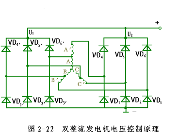
In the low speed range, due to the low generator speed, the series output of the three-phase windings increases the output voltage of the generator, which greatly improves the low-speed charging performance of the generator. In the high-speed range, as the generator speed increases, the inductive reactance of the series three-phase winding increases, the internal voltage drop increases, and the armature reaction is strengthened, causing the output voltage to drop. At this time, the original three-phase windings A, B, and C have a relatively small internal voltage drop, and the induced current is relatively large, ensuring power output at high speed.
2. The advantages of double rectifier generators are;
(1) It not only reduces the charging speed of the generator, but also ensures high-speed and high-current output, which improves the effective power of the generator. The double-rectifier generator is reduced by 200-300r/min than the normal generator minimum charging speed, and the generator can output current up to 10A at low speed; and the rated voltage and rated current is not more than 2500r/min.
(2) The structure is simple and the work is reliable. Only the number of turns of the winding is increased in the stator slot, and a set of three-phase bridge type rectification is added.
Eight-sensor sub-generator
The inductive sub-generator is also a brushless alternator consisting of a stator, a rotor, a rectifier and a casing. Its rotor is riveted from a gear-shaped steel sheet with a toothed salient pole uniformly distributed along the circumference without a field winding. Both the field winding and the armature winding are placed in the stator slot, as shown in Figure 2-23. 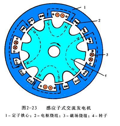
When the field winding 3 is energized by a direct current, a fixed magnetic field is generated in the stator core 1 (the upper right portion and the lower left portion are S poles; the upper left portion and the lower right portion are N poles). Since the magnetic flux of the convex portion of the rotor 4 is easily passed, the magnetic induction is maximum, thereby forming a magnetic pole. However, each convex tooth of the rotor has no fixed polarity. When it is opposite to the stator, the N pole is the S pole, and the opposite S is the N pole.
When the rotor teeth rotate in a non-moving magnetic field, the magnetic flux is the largest when the convex teeth face the stator teeth, and the magnetic flux is the smallest when the rotor slots face the protruding teeth. Therefore, when the rotor rotates, a pulsating magnetic flux is generated in the stator teeth, and an alternating electromotive force is induced in the stator windings. The armature windings are connected in a certain way and rectified to obtain direct current.
The frequency of the AC electromotive force of the armature winding in the induction sub-generator is always equal to Zn/60 (Z is the number of rotor teeth, and n is the rotor speed), which is independent of the number of magnetic pole pairs formed by the field winding, which is different from the essence of the synchronous AC machine.
The sensorless brushless alternator has a lower mass ratio than the power.
Ebike Battery,Downtube Battery,Cylinder Lithium Battery,Power Battery With Usb Port
ZHEJIANG TIANHONG LITHIUM-ION BATTERY CO.,LTD , http://www.tflbattery.com
